
Lithium ion battery outer cover material

a lithium ion battery and outer cover technology, applied in the direction of synthetic resin layered products, electric vehicles, vehicle components, etc., can solve the problems of electrolytic solution lowering the lamination strength between aluminum foil layers, metal surface corrosion, and ultimately leaking electrolytic solution to the outside, etc., to achieve superior deep-drawing formability, high quality, and adequate resistance to electrolytic solution

Active Publication Date: 2013-06-13
TOPPAN PRINTING CO LTD
View PDF1 Cites 28 Cited by
  • Summary
  • Abstract
  • Description
  • Claims
  • Application Information

AI Technical Summary

Benefits of technology

The present invention provides a lithium ion battery outer cover material that can resist electrolyte without using chromate treatment, has superior deep-drawing formability and quality, can be easily produced, and has high productivity. Furthermore, the material has superior moldability.

Problems solved by technology

If the electrolytic solution penetrates into the sealant layer, the penetrated electrolytic solution lowers lamination strength between the aluminum foil layer and the sealant layer and the electrolytic solution may ultimately leak to the outside.
However, if moisture penetrates into a deep-drawn formed product, the lithium salt ends up being hydrolyzed resulting in the formation of hydrofluoric acid, thereby causing corrosion of metal surfaces and a decrease in lamination strength between each layer of the multilayer film.
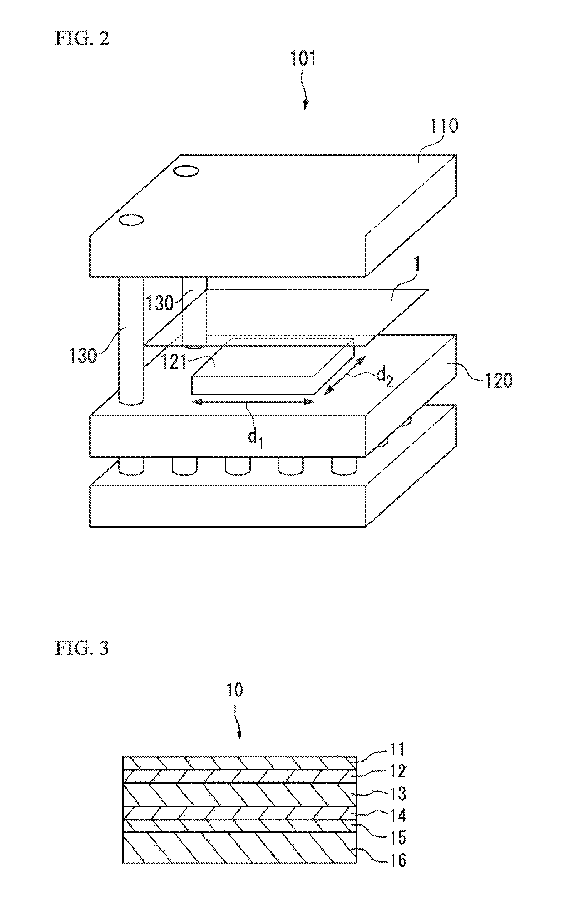
Although drawing is typically carried out with a metal mold, if the forming depth is too deep, cracks and pinholes may form in those portions of the lithium battery outer cover material that are drawn by forming, thereby resulting in a loss of reliability of the battery.
Although molding of outer cover materials is typically carried out by drawing using a metal mold, if the molding depth at this time is excessively deep, cracks and pinholes may form in those portions that are drawn by molding, thereby resulting in a loss of battery reliability.

Method used


Image

  • Lithium ion battery outer cover material
  • Lithium ion battery outer cover material
  • Lithium ion battery outer cover material

Examples


examples

[0395]Although the following provides a detailed explanation of the present invention through examples thereof, the present invention is not limited by the following descriptions.

Examples 1 to 9 and Comparative Examples 1 to 3

[0396][Materials Used]

[0397]The materials used in the present examples are as indicated below.

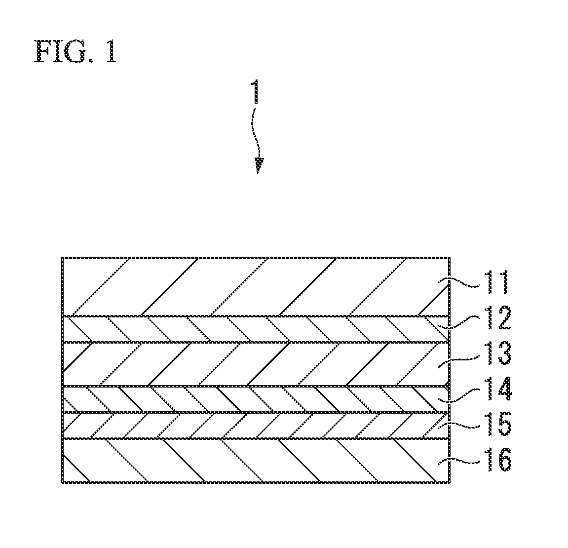
[0398](Base Material Layer 11)

[0399]The following film base materials deposited by casting were used as base materials.

[0400]Base Material SB-1: Biaxially drawn polyamide film (Unitika Ltd., ON, thickness: 25 μm)

[0401]Base Material SB-2: Biaxially drawn polyamide film (Unitika Ltd., ON-U, thickness: 25 μm)

[0402]Base Material SB-3: Biaxially drawn polyamide film (Unitika Ltd., ON-P, thickness: 25 μm)

[0403]Base Material SB-4: Biaxially drawn polyamide film (Unitika Ltd., ON, thickness: 15 μm)

[0404]Base Material SB-5: Biaxially drawn polyamide film (Unitika Ltd., ON-U, thickness: 15 μm)

[0405]Base Material SB-6: Biaxially drawn polyamide film (Unitika Ltd., ON-P, thickness...


PUM

PropertyMeasurementUnit
Fractionaaaaaaaaaa
Surface free energyaaaaaaaaaa
Contact angleaaaaaaaaaa

Abstract

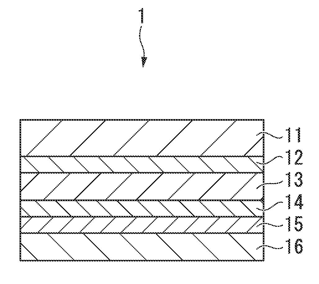
According to the present invention, a lithium ion battery outer cover material that has superior resistance to electrolytes without chromate treatment, has superior deep drawing formability and high quality, and can be produced easily is provided. The lithium ion battery outer cover material (1) of a first embodiment of the present invention has a base material layer (11), first adhesive layer (12) containing an adhesive, aluminum foil layer (13), corrosion prevention treated layer (14), second adhesive layer (15) containing an adhesive or adhesive resin, and sealant layer (16) laminated in that order. The base material layer (11) is a film base material in which the difference (α2−α1) of the elasticity (α1) to the yield point and the elasticity (α2) to the rupture point as measured according to JIS-K7127 is 100% or greater in at least one of the MD direction and TD direction.

Description

TECHNICAL FIELD[0001]The present invention relates to an outer cover material for a lithium ion battery.[0002]The present application claims priority on the basis of Japanese Patent Application No. 2010-201079 filed in Japan on Sep. 8, 2010, Japanese Patent Application No. 2010-201080 filed in Japan on Sep. 8, 2010, and Japanese Patent Application No. 2011-158849 filed in Japan on Jul. 20, 2011, the contents of which are incorporated herein by reference.BACKGROUND ART[0003]Lithium ion secondary batteries (to also be referred to as “lithium ion batteries”) are being actively developed for consumer applications used in portable terminal devices such as cell phones as well as video cameras and the like due to their high energy output despite their extremely thin shape and compact size. Metal enclosure types have conventionally been used for the outer cover materials of lithium ion batteries. However, deep-drawn formed products obtained by cold forming a laminated film having a multilay...

Claims


Application Information

Patent Timeline
IPC IPC(8): H01M2/02H01M50/105
CPCH01M2/0287B32B2605/00H01M2/024Y02T10/7011H01M2/02B32B7/12B32B15/088B32B15/20B32B27/08B32B27/32B32B27/36B32B2255/06B32B2255/10B32B2255/26B32B2270/00B32B2307/51B32B2307/516B32B2307/518B32B2307/54B32B2307/714B32B2307/7242B32B2457/00B32B2457/10H01M10/0525Y02E60/10H01M50/124H01M50/105B32B15/08Y02T10/70
Inventor SUZUTA, MASAYOSHIMURAKI, TAKUYA
Owner TOPPAN PRINTING CO LTD
Learn More