Rivet stud

a technology of riveting and securing rods, applied in the direction of fastening means, screws, dowels, etc., can solve the problems of handling and installation injuries, and achieve the effect of avoiding the risk of damage to the component and injury

Active Publication Date: 2013-05-30
NEWFREY
View PDF18 Cites 1 Cited by
  • Summary
  • Abstract
  • Description
  • Claims
  • Application Information

AI Technical Summary

Benefits of technology

[0005]The object of the invention is to create a rivet stud of the specified type that avo...

Problems solved by technology

In this design, the predetermined breaking point that is broken after the setting process forms a sharp-edged end of the profile...

Method used


Image

  • Rivet stud
  • Rivet stud
  • Rivet stud

Examples


Embodiment Construction

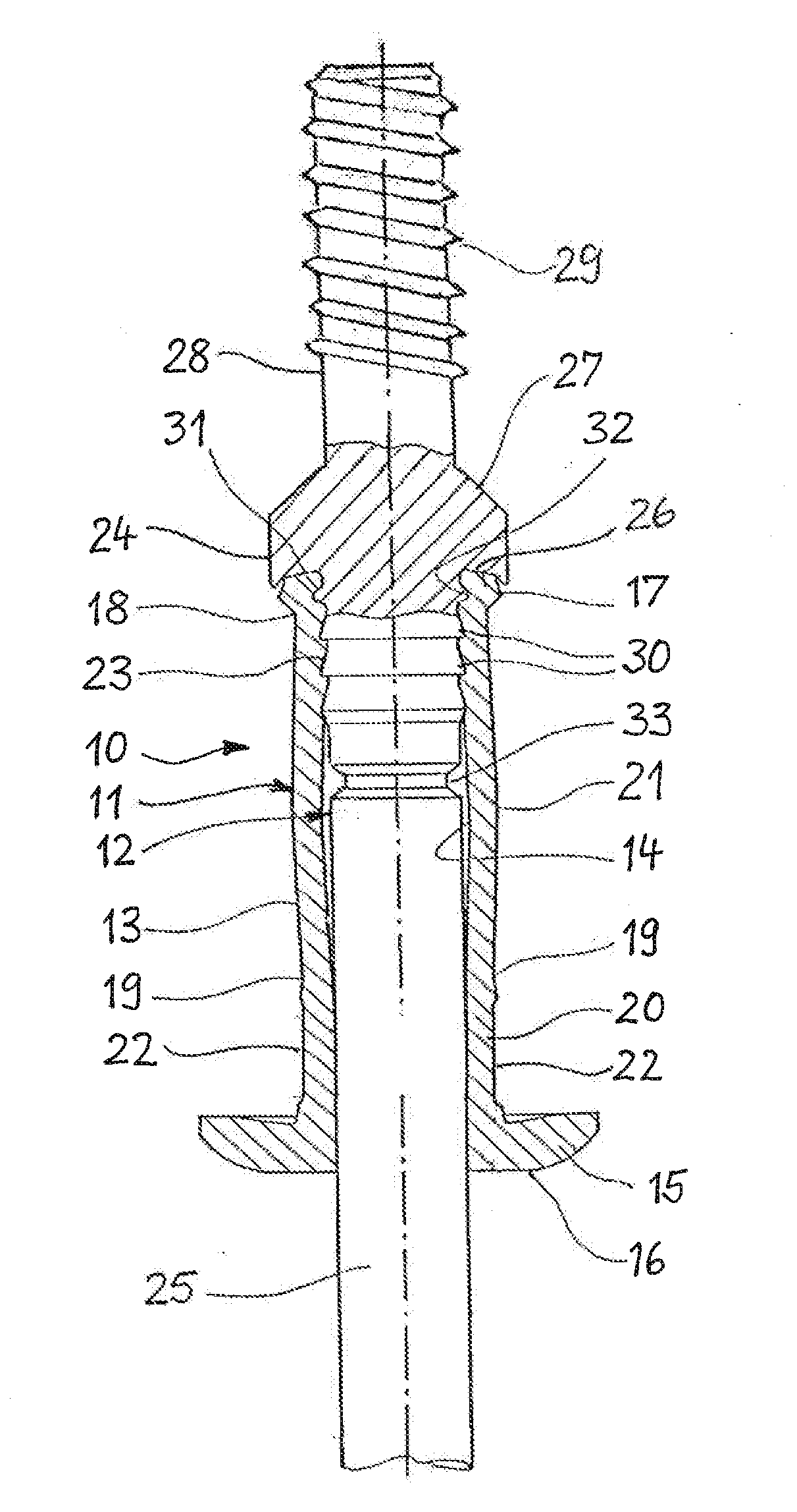
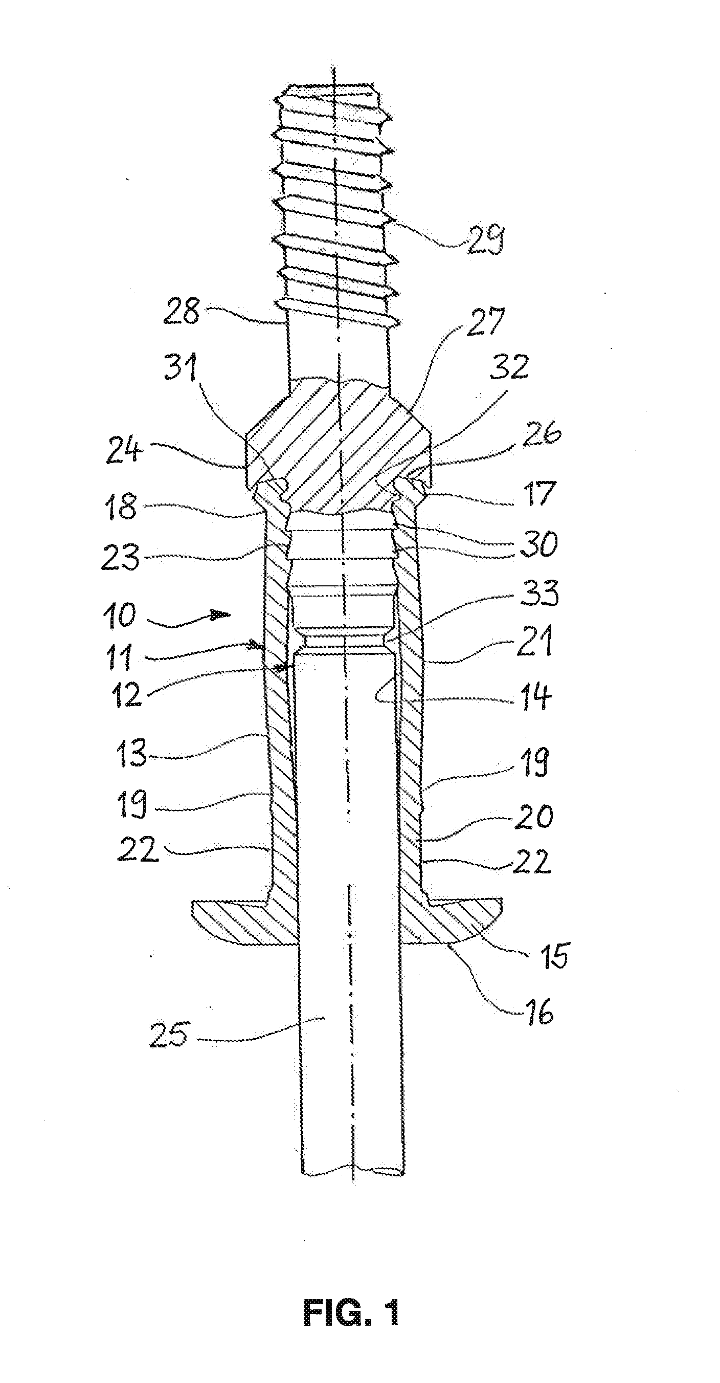
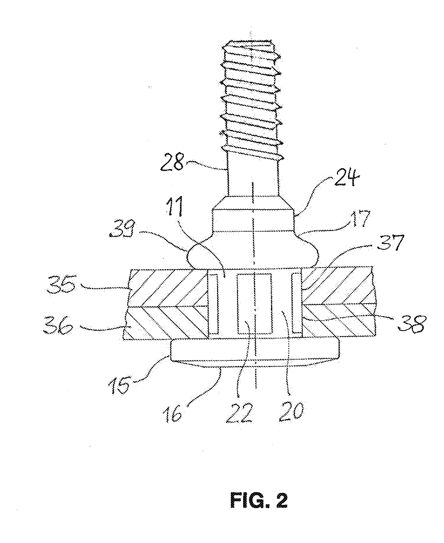
[0016]FIG. 1 shows a rivet stud 10, which is composed a rivet body 11 made of aluminum or steel, and a tension mandrel 12 made of steel. The rivet body 11 is mounted on the tension mandrel 12 and has an elongated shank 13 with a through-bore 14, in which the tension mandrel 12 is located. Formed at a head end of the shank 13 is a flange 15, which takes the form of an annular disk and is intended to contact a workpiece. The side of the flange 15 facing away from the shank 13 is provided with a flat support surface 16 for supporting the forward end of a riveting tool.

[0017]At its end opposite the flange 15, the shank 13 forms a foot end 17, which is set off from the shank 13 by a first constriction 18. A second constriction 19 divides the shank 13 into an essentially cylindrical first section 20 and a barrel-shaped second section 21 that curves slightly outward. On its outside, the first section 20 is provided with multiple flat indentations 22 spaced at regular intervals from one ano...


PUM


Abstract

A rivet stud has a rivet body with an elongated shank, a flange, and an axial bore in which is located a tension mandrel, which has a mandrel shank with a drawing end projecting out of a head end of the rivet body that is separable from the mandrel shank at a predetermined breaking point and which has a mandrel head that is supported on a foot end of the rivet body. The mandrel shank is provided with locking means that secure it in the rivet body after setting of the rivet stud, and the predetermined breaking point is located such that the breaking point lies inside the bore of the rivet body after setting of the rivet stud. Located on the mandrel head is a mounting stud that projects from the mandrel head on the side opposite the mandrel shank.

Description

CROSS-REFERENCE TO RELATED APPLICATIONS[0001]This application claims priority from German Patent Application No. DE 102011055724.5, filed on Nov. 25, 2011, the disclosure of which is incorporated herein by referenceBACKGROUND OF THE INVENTION[0002]The invention concerns a rivet stud, having a rivet body that has an elongated shank with a head end, a foot end, and an axial bore, wherein the shank is intended to be inserted foot end first into an opening in a workpiece and a radially extending flange that serves to make contact with one side of the workpiece is located at the head end, and said rivet stud having, located in the bore of the rivet body, a tension mandrel, which has a mandrel shank with a drawing end projecting out of the head end of the rivet body that is separable from the mandrel shank at a predetermined breaking point, and which mandrel has a mandrel head that is supported by the foot end of the rivet body in order to transmit a force to the rivet body during setting...

Claims


Application Information

Patent Timeline
IPC IPC(8): F16B19/10
CPCF16B19/1027F16B35/06F16B19/1054
Inventor SCHNEIDER, STEFANSALTENBERGER, REIMAR
Owner NEWFREY
Why Eureka
Try Eureka