Rivet stud

a technology of riveting and securing rods, applied in the direction of fastening means, screws, dowels, etc., can solve the problems of handling and installation injuries, and achieve the effect of avoiding the risk of damage to the component and injury

Active Publication Date: 2014-04-15
NEWFREY
View PDF18 Cites 3 Cited by
  • Summary
  • Abstract
  • Description
  • Claims
  • Application Information

AI Technical Summary

Benefits of technology

[0005]The object of the invention is to create a rivet stud of the specified type that avoids the risk of damage to the component and the risk of injury during installation and handling.
[0009]The rivet stud, and in particular the rivet body, is designed according to the invention in such a manner that, during the setting process, the rivet body forms a disk on the blind side of the penetrated workpiece that rests uniformly against the workpiece. The formation of the disk supports an orientation of the rivet stud perpendicular to the surface of the workpiece, since the axial clamping force acting between the mandrel head and the flange during setting generates a moment of force that tends to move the rivet stud into a perpendicular position. The disk formed by the rivet body also increases resistance to loads on the set rivet mandrel that are oriented perpendicular to the longitudinal axis of the rivet body. During the setting process, the disk formed by the bulging of the rivet body moves axially against the workpiece, wherein the radial expansion of the rivet body is reduced within the opening of the workpiece. As a result, the rivet stud is also suitable for placement in thin and soft workpieces. The disk-shaped bulging of the rivet body also reduces the tendency of the rivet body to pull into the opening of the workpiece during setting.
[0011]The rivet stud according to the invention presents advantages and application possibilities. The anchoring of the rivet stud in one or more workpieces ensures high resistance to pull-out, since the rivet stud is supported on the workpiece by its flange, which can be made to have large dimensions, particularly when the mounting stud is under tensile loading. Due to the interlocking connection of the tension mandrel and rivet body, and the contact pressure of the disk-shaped setting head, the anchoring of the rivet stud in the workpiece can withstand high dynamic loads. The connection between the rivet stud and workpiece is impervious to splash water.
[0012]Setting of the rivet stud according to the invention can be carried out easily and quickly, and only requires one side of the workpiece to be accessible. Setting of the rivet stud can be performed fully automatically using existing blind rivet installation tools, but can also be done with simple hand-operated tools, and its use requires little training. The rivet stud can be set in soft materials in which it is not possible to use other methods, such as stud welding, adhesive stud bonding, self-piercing riveting, press fit studs, etc. The rivet stud can be set in a single workpiece or can join multiple workpieces together by setting. As a result, it is suitable for joining multilayered components without limitation with regard to the arrangement of the individual layers, their materials, or their thicknesses. The rivet stud can be set in even the thinnest-walled materials, such as films of 0.1 mm. On the other hand, it can have a wide clamping range, for example in material thicknesses from 1.5 to 5 mm for a rivet body diameter of 4.8 mm. Consequently, multiple components can be joined, and the requirement for different versions of rivet studs is low as a result. The rivet stud does not place any special requirements on the surface finish of the workpiece, and does not damage existing anti-corrosion coatings on the workpiece.

Problems solved by technology

In this design, the predetermined breaking point that is broken after the setting process forms a sharp-edged end of the profile stud that can lead to damage of parts to be installed on the profile stud and can result in injuries during handling and installation.

Method used


Image

  • Rivet stud
  • Rivet stud
  • Rivet stud

Examples


Embodiment Construction

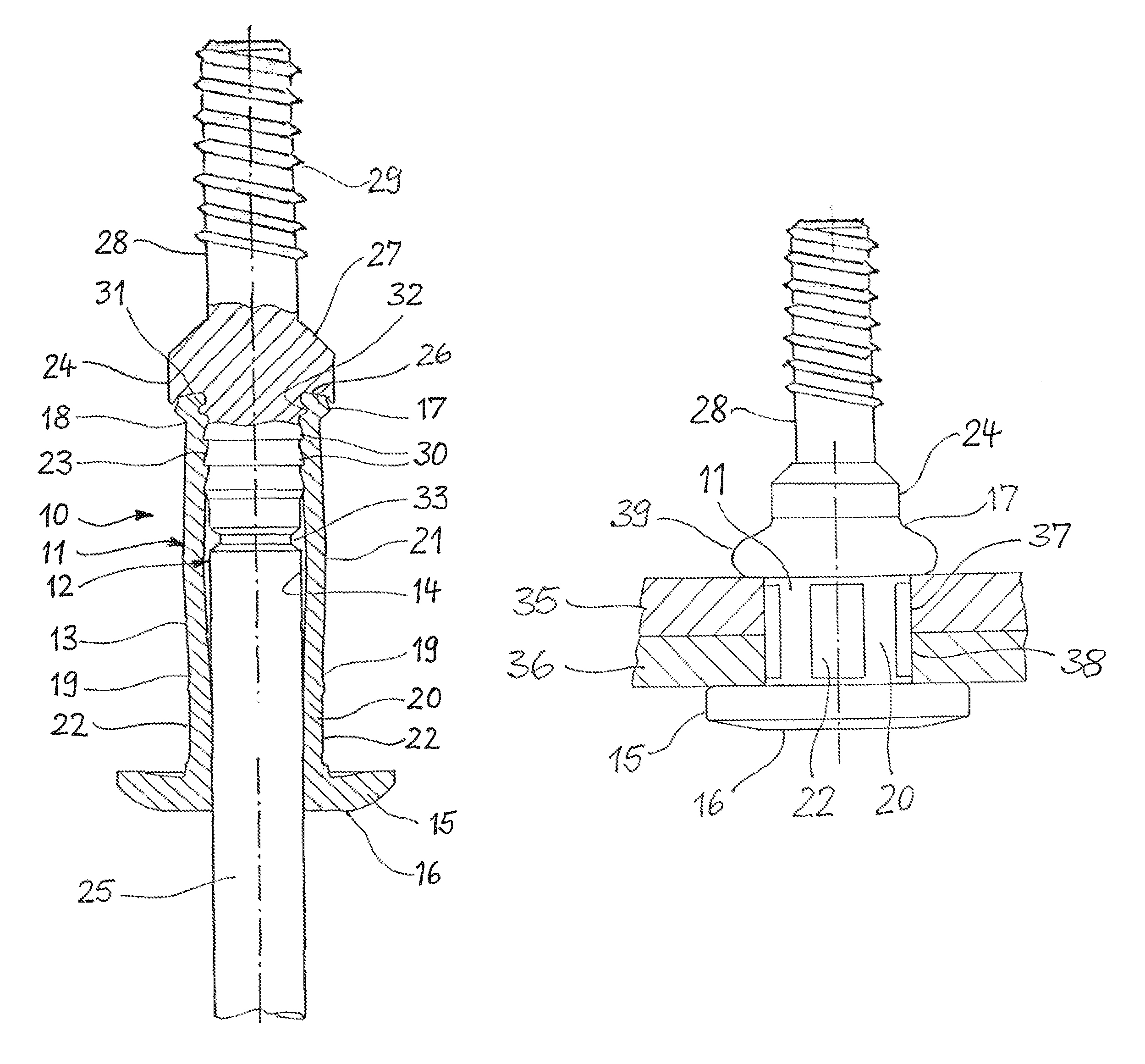
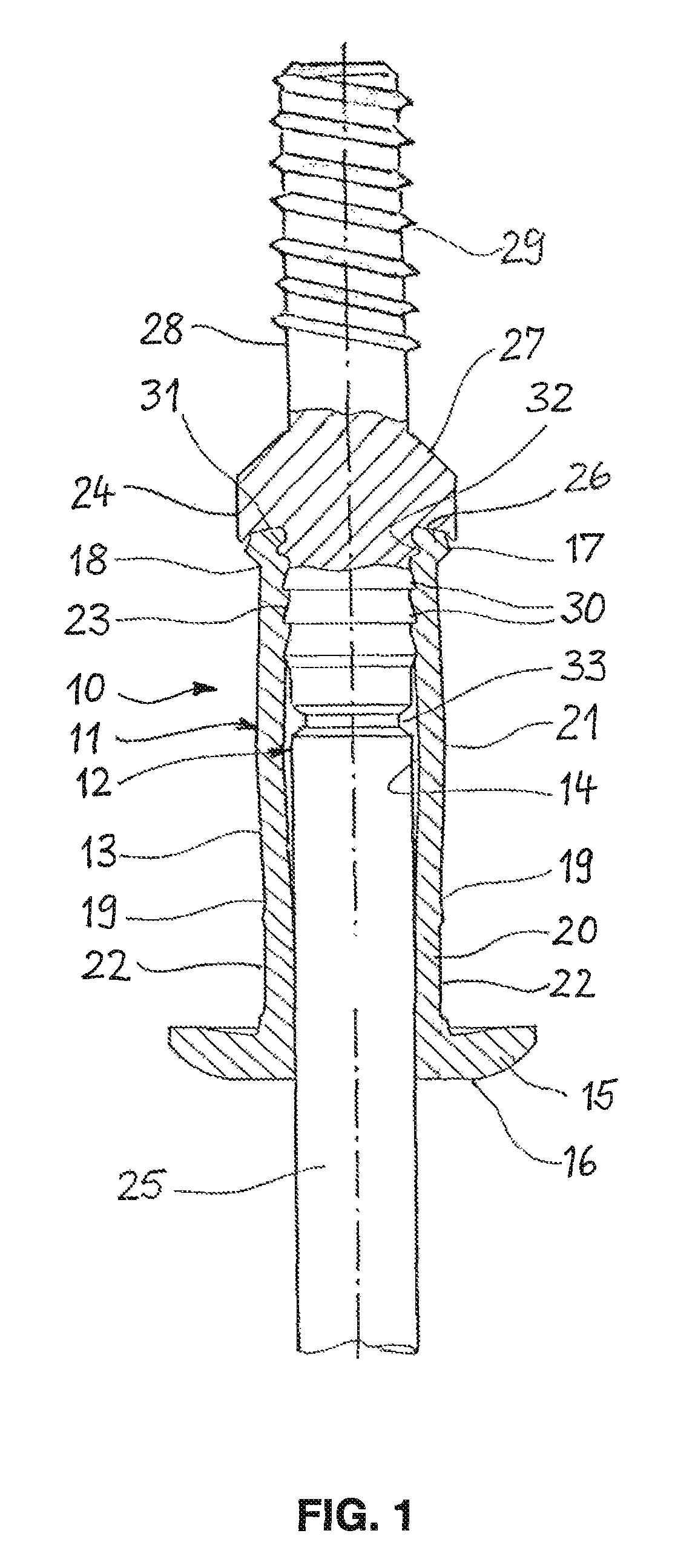
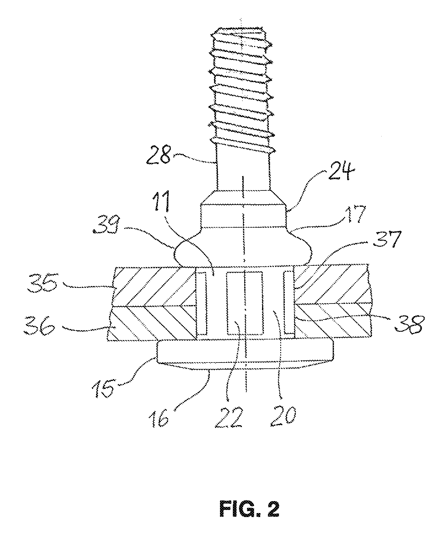
[0016]FIG. 1 shows a rivet stud 10, which is composed a rivet body 11 made of aluminum or steel, and a tension mandrel 12 made of steel. The rivet body 11 is mounted on the tension mandrel 12 and has an elongated shank 13 with a through-bore 14, in which the tension mandrel 12 is located. Formed at a head end of the shank 13 is a flange 15, which takes the form of an annular disk and is intended to contact a workpiece. The side of the flange 15 facing away from the shank 13 is provided with a flat support surface 16 for supporting the forward end of a riveting tool.

[0017]At its end opposite the flange 15, the shank 13 forms a foot end 17, which is set off from the shank 13 by a first constriction 18. A second constriction 19 divides the shank 13 into an essentially cylindrical first section 20 and a barrel-shaped second section 21 that curves slightly outward. On its outside, the first section 20 is provided with multiple flat indentations 22 spaced at regular intervals from one ano...


PUM


Abstract

A rivet stud has a rivet body with an elongated shank, a flange, and an axial bore in which is located a tension mandrel, which has a mandrel shank with a drawing end projecting out of a head end of the rivet body that is separable from the mandrel shank at a predetermined breaking point and which has a mandrel head that is supported on a foot end of the rivet body. The mandrel shank is provided with locking means that secure it in the rivet body after setting of the rivet stud, and the predetermined breaking point is located such that the breaking point lies inside the bore of the rivet body after setting of the rivet stud. Located on the mandrel head is a mounting stud that projects from the mandrel head on the side opposite the mandrel shank.

Description

CROSS-REFERENCE TO RELATED APPLICATIONS[0001]This application claims priority from German Patent Application No. DE 102011055724.5, filed on Nov. 25, 2011, the disclosure of which is incorporated herein by reference.BACKGROUND OF THE INVENTION[0002]The invention concerns a rivet stud, having a rivet body that has an elongated shank with a head end, a foot end, and an axial bore, wherein the shank is intended to be inserted foot end first into an opening in a workpiece and a radially extending flange that serves to make contact with one side of the workpiece is located at the head end, and said rivet stud having, located in the bore of the rivet body, a tension mandrel, which has a mandrel shank with a drawing end projecting out of the head end of the rivet body that is separable from the mandrel shank at a predetermined breaking point, and which mandrel has a mandrel head that is supported by the foot end of the rivet body in order to transmit a force to the rivet body during settin...

Claims


Application Information

Patent Timeline
Patent Type & Authority Patents(United States)
IPC IPC(8): F16B13/04
CPCF16B19/1027F16B19/1054F16B35/06
Inventor SCHNEIDER, STEFANSALTENBERGER, REIMAR
Owner NEWFREY
Why Eureka
Try Eureka