System for charging electrical storage device and method of making same

Active Publication Date: 2013-05-30
GENERAL ELECTRIC CO
View PDF9 Cites 16 Cited by
  • Summary
  • Abstract
  • Description
  • Claims
  • Application Information

AI Technical Summary

Benefits of technology

The invention is a propulsion system that uses a motor drive and a DC link with two power switches. The system also includes an inductor and an energy storage device to create charging energy. Another aspect of the invention is a control system that interleaves the power switches to create a voltage difference between the two nodes and generates the charging voltage using a transformer. The technical effects of this invention include improved efficiency and control over charging of the energy storage device.

Problems solved by technology

This additional DC-DC converter, however, adds cost and weight to the vehicle.

Method used


Image

  • System for charging electrical storage device and method of making same
  • System for charging electrical storage device and method of making same
  • System for charging electrical storage device and method of making same

Examples


Embodiment Construction

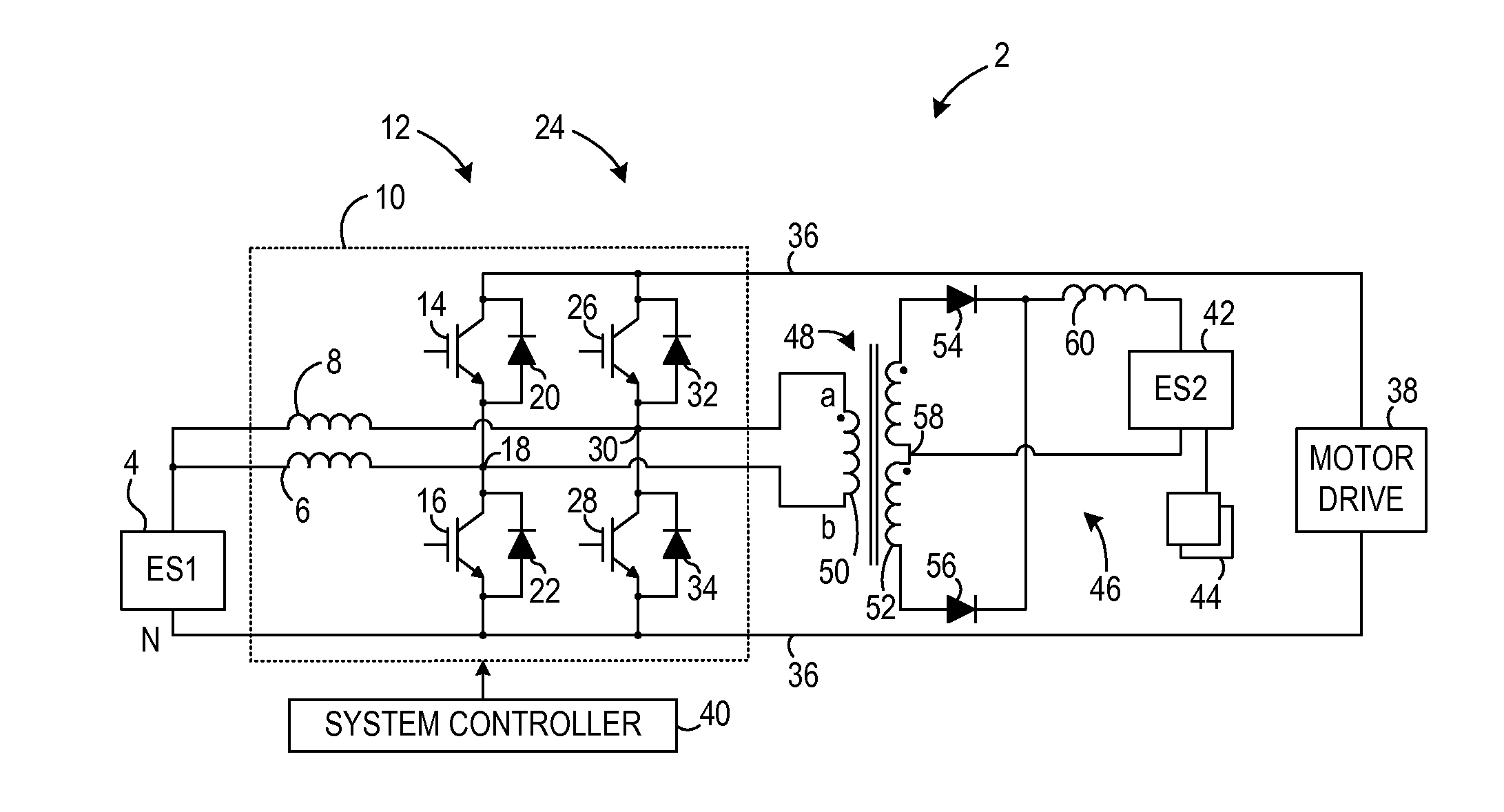
[0020]FIG. 1 illustrates a schematic diagram of a traction system 2 usable in a vehicle, such as a plug-in electric or plug-in hybrid vehicle, or stationary electric drive system is shown in accordance with an embodiment of the invention. Traction system 2 includes a first energy storage device 4, which may be a battery, a fuel cell, an ultracapacitor, or the like, coupled to a pair of inductors 6, 8 of a bi-directional DC-DC voltage converter assembly 10. Inductor 6 is coupled to a first leg 12 including a first power switch 14 and a second power switch 16 connected in series at a first node 18. As used herein, a power switch may be a bipolar junction transistor (BJT), a metal-oxide-semiconductor field-effect transistor (MOSFET), an insulated gate bipolar transistors (IGBT), a contactor, or another power switch as known in the art. Each of the power switches 14, 16 is coupled in anti-parallel with a first and second diode 20, 22, respectively. In addition, inductor 8 is coupled to ...


PUM

PropertyMeasurementUnit
Electric potential / voltageaaaaaaaaaa
Frequencyaaaaaaaaaa
Energyaaaaaaaaaa

Abstract

A system for charging an electrical storage device includes a motor drive, a DC link electrically coupled to the motor drive, and a first leg coupled to the DC link that includes a first power switch coupled in series with a second power switch via a first node. A first inductor is coupled to the first node, and a first energy storage device (ESD) is electrically coupled to the first inductor. A second leg is coupled to the DC link that includes a third power switch coupled in series with a fourth power switch via a second node. A charging circuit includes a transformer coupled to the first and second nodes. A second ESD is coupled to receive charging energy from the transformer, and a controller is configured to cause a first voltage mismatch between the first and second nodes to generate the charging energy.

Description

BACKGROUND OF THE INVENTION[0001]Embodiments of the invention relate generally to hybrid and electric vehicles and, more particularly, to transferring energy from one energy storage device (ESD) to another ESD of a traction system.[0002]A hybrid electric vehicle (HEV) may combine an internal combustion engine and an electric motor powered by an energy storage device, such as a traction battery, to propel the vehicle. Typically, the electric motor of an HEV is coupled between the internal combustion engine and the transmission to take advantage of the torque increase through the transmission. Such a combination may increase overall fuel efficiency by enabling the combustion engine and the electric motor to each operate in respective ranges of increased efficiency. Electric motors, for example, may be efficient at accelerating from a standing start, while combustion engines may be efficient during sustained periods of constant engine operation, such as in highway driving. Having an el...

Claims


Application Information

Patent Timeline
IPC IPC(8): H02J7/00H01R43/00H02J1/00
CPCY10T29/49117H02M3/158H02M3/335H02M2001/009H02J7/1423H02J7/1438H02J1/08B60L1/003B60L7/14B60L15/007B60L2200/22B60L2210/14B60L2240/547B60L2240/622Y02T90/16B60L50/40B60L50/51B60L58/12B60L58/40H02J2310/48Y02T10/64Y02T10/70Y02T10/72H02M1/009Y02T90/40
Inventor KANAKASABAI, VISWANATHAN
Owner GENERAL ELECTRIC CO
Why Eureka
Try Eureka