Hydraulic Mining System for Tabular Orebodies Utilising Directional Drilling

a mining system and hydraulic technology, applied in the direction of borehole/well accessories, fluid removal, dislodge machines, etc., can solve the problems of roof cave in and form a goaf or gob, large amount of coal required for the production of heat and electrical energy in use today, and high cost, so as to achieve cost saving, easy movement, and short period of time

Inactive Publication Date: 2013-05-23
GRAY IAN
View PDF1 Cites 6 Cited by
  • Summary
  • Abstract
  • Description
  • Claims
  • Application Information

AI Technical Summary

Benefits of technology

[0015]It can be appreciated that rather than using expensive and extremely heavy machinery for longwall mining, essentially the same result can be accomplished using directional drilling to sequentially form boreholes between roadways, and then use a high pressure jet which traverses each borehole to erode the ore panel. The mining of the ore continues in each borehole until the panel is spent. According to this technique, the equipment can be easily moved from one ore panel to another in a short period of time, thereby making the technique very cost effective. The nature of the equipment means that it can be easily retrieved should a collapse of the borehole or face occur. Another borehole may then be drilled and the mining process is recommenced through erosion. In the event that the drill string is lost then its cost is small compared to that of conventional longwall equipment.

Problems solved by technology

Similarly, the production of much of the heat and electrical energy in use today requires a substantial amount of coal.
The removal of the pillars causes the roof to cave in and form a goaf or gob.
Because of the complexity and size of such mining machines, they are extremely expensive.
The hydraulic mining system is particularly suited to the underground environment where the ore is weak and the roof and floor rocks are hard to provide support and guard against cave in of the roof.
Limitations of hydraulic jet mining include the effective dispersal range of the jet, which is approximately 30 m, and the limited visibility afforded to the operators.

Method used


Image

  • Hydraulic Mining System for Tabular Orebodies Utilising Directional Drilling
  • Hydraulic Mining System for Tabular Orebodies Utilising Directional Drilling
  • Hydraulic Mining System for Tabular Orebodies Utilising Directional Drilling

Examples


Embodiment Construction

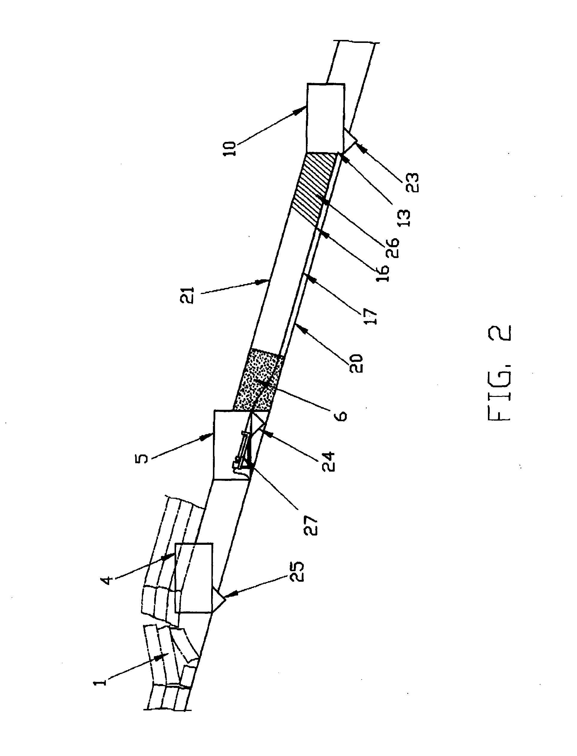
[0022]FIG. 1 illustrates a plan view of a mineral panel that is being mined by drilling down dip. The mining operation of the panel proceeds in the drawing of FIG. 1 to the right, with the goaf (2) to the left and the unmined orebody (3) to the right. The angle or dip of the panel of ore being mined is shown in FIG. 2, where the gateroad (10) is lower in elevation than the gateroad (5). The panel of ore of interest includes the solid deposit of ore (3) to be mined, as well as the goaf (2) that has been mined. The dip direction is marked by an arrow (18) in FIG. 1. illustrated also is a neighbour goaf (1) that was formed in the area of the previously mined neighbour panel. The neighbour goaf (1) is separated from the current mining panel, i.e. solid ore (3) and associated goaf (2), by gateroads (4, 5). On the lower side of the panel (2, 3) undergoing the mining operation are the lower elevation gateroads (10, 11). The gateroads (4, 5, 10, 11) slope downhill to the right of the figure...


PUM


Abstract

A mining system for extracting ore using directional chilling techniques to obtain access to the orebody. Spaced-apart roadways are formed in the ore formation, with a downhill roadway being lower in elevation than the other roadway, and the downhill roadway having a ditch therein draining downhill. A borehole is formed between roadways in the ore formation using the directional drill bit, and then the end of the drill string is equipped with a jetting nozzle. The jetting nozzle is moved within the borehole to erode the formation and mine the ore. In one embodiment, a slurry of mined ore and jetting fluid flows as a slurry down the intersection of the mined face and the floor towards a ditch formed in the downhill roadway. In another embodiment, a slurry of the mined ore and the jetting fluid flows down the borehole, and then down the ditch formed in the downhill roadway. In each case, the ore flows down the downhill roadway to a sump. From the sump, the ore is carried to the surface for transportation and eventual refining or use.

Description

RELATED PATENT APPLICATIONS[0001]This PCT application claims the further benefit of Australian provisional application 2010903253 filed on 21 Jul. 2010, and Australian provisional application 2011900008 filed on 1 Jan. 2011.BACKGROUND OF THE INVENTION[0002]The production of many goods for commercial and private use requires the utilisation of numerous types of minerals, or orebodies, and the processing of the same from raw materials into finished goods. Similarly, the production of much of the heat and electrical energy in use today requires a substantial amount of coal. The minerals utilised in industry are obtained from the crust of the earth, usually by mining the same. Before mining machines were in general use, the mining of minerals was carried out manually by using picks and shovels, as well as wagons pulled by horses or mules. In order to increase the production level of minerals, mining machines were invented to allow the minerals to be more easily mined from the earth and ...

Claims


Application Information

Patent Timeline
Patent Type & Authority Applications(United States)
IPC IPC(8): E21C45/00
CPCE21B43/292E21F13/04E21C45/00
Inventor GRAY, IAN
Owner GRAY IAN
Why Eureka
Try Eureka