
Optical functional film, and method for manufacturing liquid crystal display device using same

a technology of optical functional film and liquid crystal display device, which is applied in the direction of instruments, polarising elements, paper/cardboard articles, etc., can solve the problems of complicated unpacking process, long process time, and a lot of necessary packing materials

Active Publication Date: 2013-05-23
NITTO DENKO CORP
View PDF2 Cites 9 Cited by
  • Summary
  • Abstract
  • Description
  • Claims
  • Application Information

AI Technical Summary

Benefits of technology

The method described in this patent prevents bubbles from forming when bonding an optical functional film to a liquid crystal panel. It also reduces the likelihood of the carrier film breaking, resulting in high-quality products with a high yield. The optical functional film is preferably drawn from a roll, which allows for continuous bonding and easy delivery of the finished product.

Problems solved by technology

Unfortunately, this process has problems such as long process time, a lot of necessary packing materials, and complicated unpacking process.

Method used


Image

  • Optical functional film, and method for manufacturing liquid crystal display device using same
  • Optical functional film, and method for manufacturing liquid crystal display device using same
  • Optical functional film, and method for manufacturing liquid crystal display device using same

Examples


example 1

[0113]To a four-neck flask equipped with a nitrogen gas introducing tube and a condenser were added 95 parts of butyl acrylate (BA), 5 parts of acrylic acid (AA), 0.1 parts of 2,2-azobisisobutyronitrile, and 140 parts of ethyl acetate. After the air was sufficiently replaced with nitrogen gas, the mixture was subjected to a polymerization reaction at 55° C. for 8 hours with stirring under a nitrogen stream, so that a high molecular weight polymer A with a weight average molecular weight of 1,700,000 was obtained.

[0114]Based on 100 parts of the solid in the resulting polymer solution, 0.5 parts of a polyisocyanate crosslinking agent (CORONATE L (product name) manufactured by NIPPON POLYURETHANE INDUSTRY CO., LTD.) including a trimethylolpropane-tolylene diisocyanate adduct, and 3-glycidoxypropyltrimethoxysilane (KBM403 (product name) manufactured by SHIN-ETSU CHEMICAL CO., LTD.) were added to the polymer solution. The resulting pressure-sensitive adhesive composition was then applied...

examples 2 to 7

[0116]Continuous rolls each composed of a carrier film and a pressure-sensitive adhesive layer-carrying polarizing film were obtained under the same conditions as those in Example 1, except that the carrier film was changed as shown in Table 1. The carrier films used in the examples and the comparative examples are shown in Table 1.

TABLE 1LongitudinalThicknesselastic modulusProduct name[μm][MPa]TORAY LUMIRROR F574.54000TORAY LUMIRROR F536.34000TORAY LUMIRROR S10124000Mitsubishi MRF25254500TORAY TORAYFAN 940730690Mitsubishi MRF38CK384000TORAY LUMIRROR X20385000TORAY LUMIRROR E60503200Mitsubishi MRN50504600Mitsubishi MRF75CK753900


PUM

PropertyMeasurementUnit
elastic modulusaaaaaaaaaa
thicknessaaaaaaaaaa
longitudinal elastic modulusaaaaaaaaaa

Abstract

Provided is an optical functional film in which air bubbles can be effectively prevented from forming during lamination, and preferably in which a carrier film does not tear readily. Also provided is a method for manufacturing a liquid crystal display device using this optical functional film. A belt-shaped optical functional film is used in order to cut away the optical functional film at predetermined intervals from the belt-shaped optical functional film to which a carrier film is bonded, with the carrier film remaining uncut; to subsequently turn over the carrier film by an edge-shaped member and peel away the optical functional film; and to laminate the exposed surface of the optical functional film to a sheet member while the optical functional film is being peeled away, wherein the optical functional film is characterized in that the flexural rigidity of the carrier film per unit length in the longitudinal direction is from 5.0×10⁻⁵ N·mm2 to 8.0×10⁻² N·mm2, and the longitudinal modulus in the longitudinal direction is from 3000 MPa to 5000 MPa.

Description

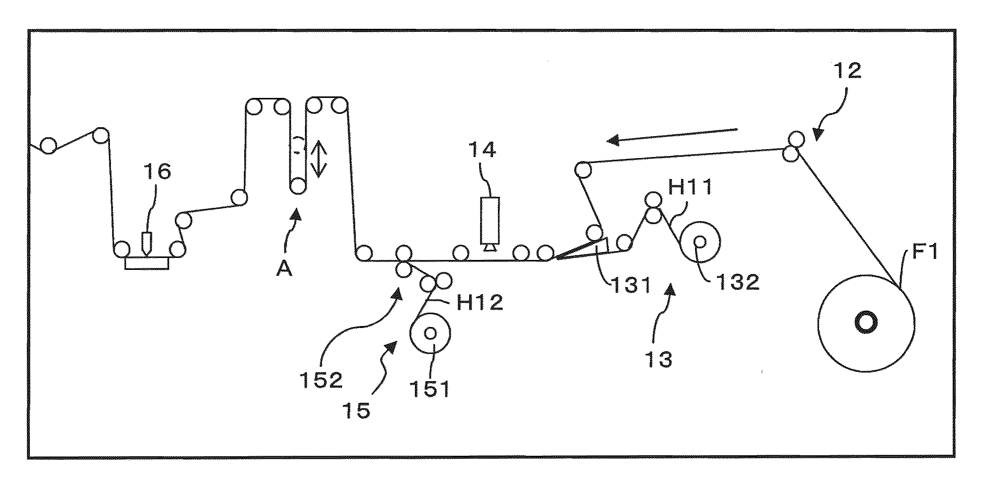
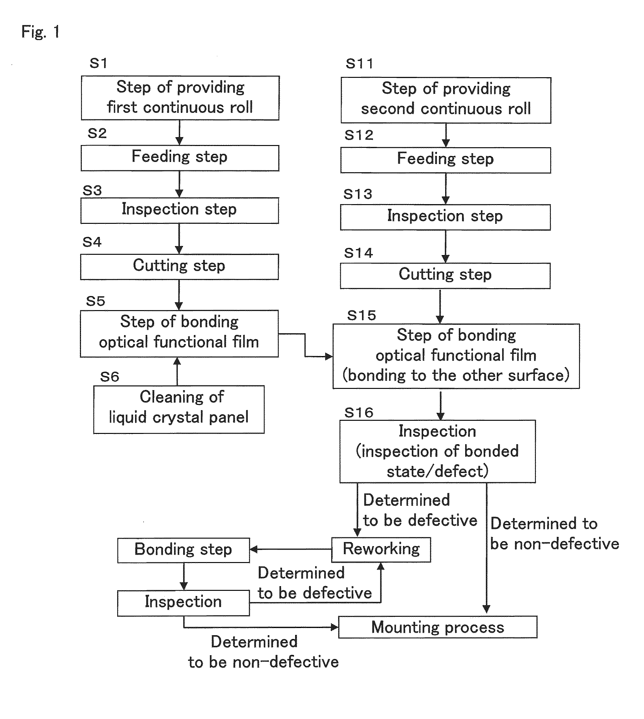
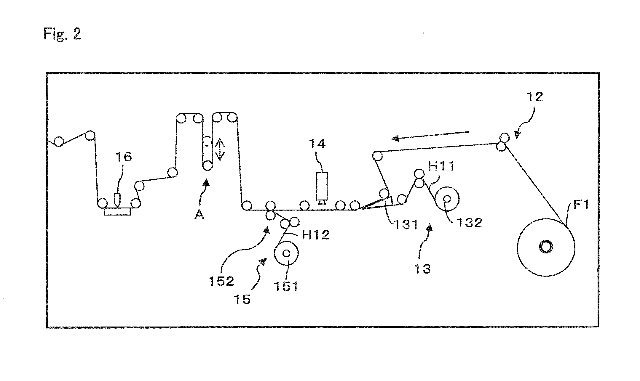
TECHNICAL FIELD[0001]The invention relates to an optical functional film that includes a belt-shaped optical functional film and a carrier film bonded thereto and is for use in a process including cutting the belt-shaped optical functional film at predetermined intervals while leaving the carrier film uncut, then peeling off the cut piece of the optical functional film from the carrier film by turning the direction of the feeding of the carrier film by means of an edge member, and bonding the exposed surface of the cut piece of the optical functional film to a flat piece member while peeling off the cut piece of the optical functional film. The invention also relates to a method for manufacturing an optical display device using such an optical functional film.BACKGROUND ART[0002]In the conventional art, to deliver optical functional films to liquid crystal display device manufacturers, optical functional film manufactures perform a process including providing a roll of a flat piece ...

Claims


Application Information

Patent Timeline
Patent Type & Authority Applications(United States)
IPC IPC(8): B32B7/06B32B38/00
CPCB32B37/003G02F1/1303B32B2307/40Y10T428/14B32B7/06B32B38/0004G02F1/133528B32B2457/202Y10T156/1052G02B5/30G02F1/1335
Inventor HIRATA, SATOSHIKITADA, KAZUOYURA, TOMOKAZUKOSHIO, SATORUNAKAZONO, TAKUYA
Owner NITTO DENKO CORP
Learn More