Nitric oxide detection element
- Summary
- Abstract
- Description
- Claims
- Application Information
AI Technical Summary
Benefits of technology
Problems solved by technology
Method used
Image

Examples
embodiment 1
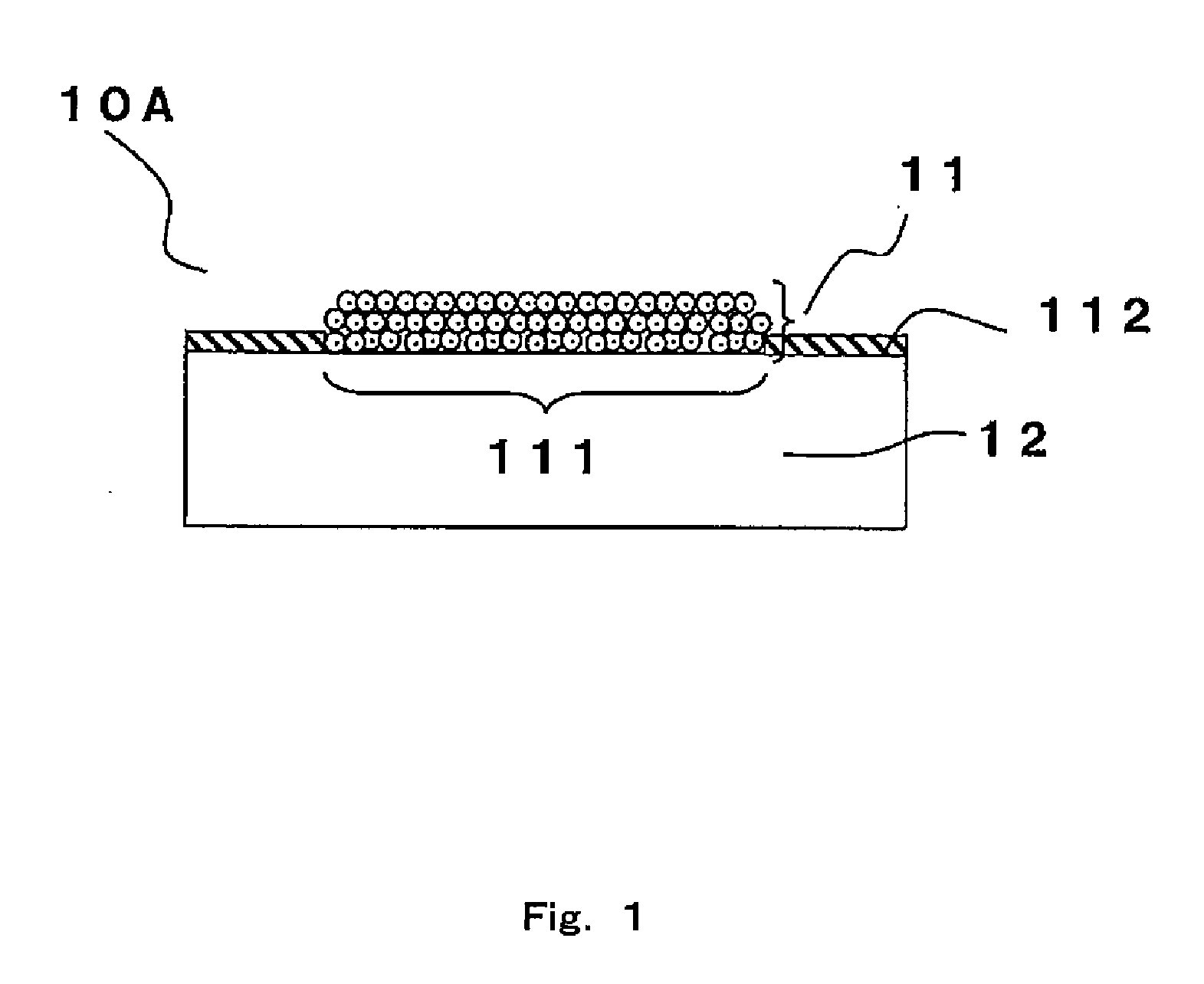
[0034]FIG. 1 is a cross-sectional conceptual diagram showing a nitric oxide detection element 10A according to Embodiment 1. As shown in FIG. 1, a sensing film 11 is fixed on the surface of a substrate 12. Patterning is performed in advance on the surface of the substrate 12, and the surface is divided into a sensing film portion 111 and a peripheral portion 112. The sensing film 11 is formed on the sensing film portion 111.
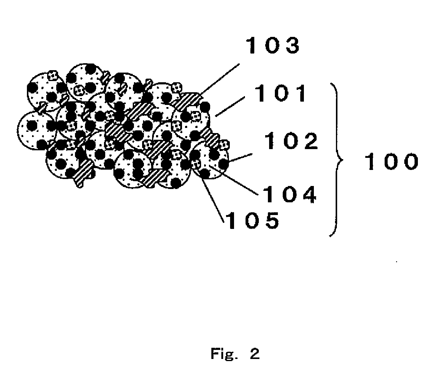
[0035]FIG. 2 is an enlarged conceptual diagram showing a relationship among materials forming the sensing film 11 of FIG. 1. As shown in FIG. 2, a dye 102 and a radical scavenger 105 are supported on the surfaces of inorganic particles 101, and thus nitric oxide sensing particles 100 are formed. Preferably, a non-ionic surfactant 104 is used, the presence of which suppresses the dye 102 and the radical scavenger 105 from aggregating together. Accordingly, the dye 102 and the radical scavenger 105 are supported on the surfaces of the inorganic particles 101 in a d...
embodiment 2
[0130]FIG. 10 is an enlarged conceptual diagram showing a relationship among materials forming a nitric oxide detection element according to Embodiment 2. In Embodiment 2, a dye 40 and a radical scavenger 42 are directly supported on the surface of a support 41. The dye and the radical scavenger are the same as those described in Embodiment 1. Similar to Embodiment 1, a non-ionic surfactant may be used in Embodiment 2. However, the use of a non-ionic surfactant is not essential.
[0131]For example, filter paper, a nonwoven fabric, or a woven fabric may be used as the support 41. Examples of a material forming the filter paper include a cellulosic material, a non-cellulosic material, glass fiber, PTFE, and a mixture of these. Preferably, the nitric oxide detection element according to the present invention exhibits an optical absorptance of 10% to 30% in the Soret band; the NO sensitivity of the nitric oxide detection element is a differential optical reflectance of 5% or higher; and t...
embodiment 3
[0136]FIG. 11 is an enlarged conceptual diagram showing a relationship among materials forming a nitric oxide detection element according to Embodiment 3. In Embodiment 3, inorganic particles are not used, and a dye 50 and a radical scavenger 51 are dispersed within a polymer adhesive 52. A sensing film made of such a polymer adhesive 52 is formed on the surface of the substrate 12 (not shown). In Embodiment 3, the same dye, radical scavenger, polymer adhesive, and substrate as those described in Embodiment 1 are used.
[0137]Hereinafter, an example of a method of fabricating the nitric oxide detection element according to Embodiment 3 is described.
[0138]CoTP(4-OCH3)P in which Xi=OCH3 as the dye 50 was dissolved in a chloroform solvent; DMPO as the radical scavenger 51 was dissolved in the chloroform solvent; and PEO as the polymer adhesive 52 was dissolved in the chloroform solvent. In this manner, a preparation solution was prepared. At the time, the dye concentration was adjusted t...
PUM
 Abstract
Description
Claims
Application Information
 - R&D
- Intellectual Property
- Life Sciences
- Materials
- Tech Scout
- Unparalleled Data Quality
- Higher Quality Content
- 60% Fewer Hallucinations
Browse by: Latest US Patents, China's latest patents, Technical Efficacy Thesaurus, Application Domain, Technology Topic, Popular Technical Reports.
© 2025 PatSnap. All rights reserved.Legal|Privacy policy|Modern Slavery Act Transparency Statement|Sitemap|About US| Contact US: help@patsnap.com