
Vehicle with a cooling system for cooling and method for cooling in a vehicle

Active Publication Date: 2013-05-23
AIRBUS OPERATIONS GMBH
View PDF20 Cites 5 Cited by
  • Summary
  • Abstract
  • Description
  • Claims
  • Application Information

AI Technical Summary

Benefits of technology

The invention proposes a vehicle with a cooling system to reduce heat generated by heat-emitting devices, which can lower fuel consumption. The method involves cooling the devices while in use to prevent overheating. This technology helps to keep vehicles running more efficiently and reduces the amount of fuel consumed while driving.

Problems solved by technology

However, this may have a negative effect on the fuel consumption of the vehicle.

Method used


Image

  • Vehicle with a cooling system for cooling and method for cooling in a vehicle
  • Vehicle with a cooling system for cooling and method for cooling in a vehicle
  • Vehicle with a cooling system for cooling and method for cooling in a vehicle

Examples


Embodiment Construction

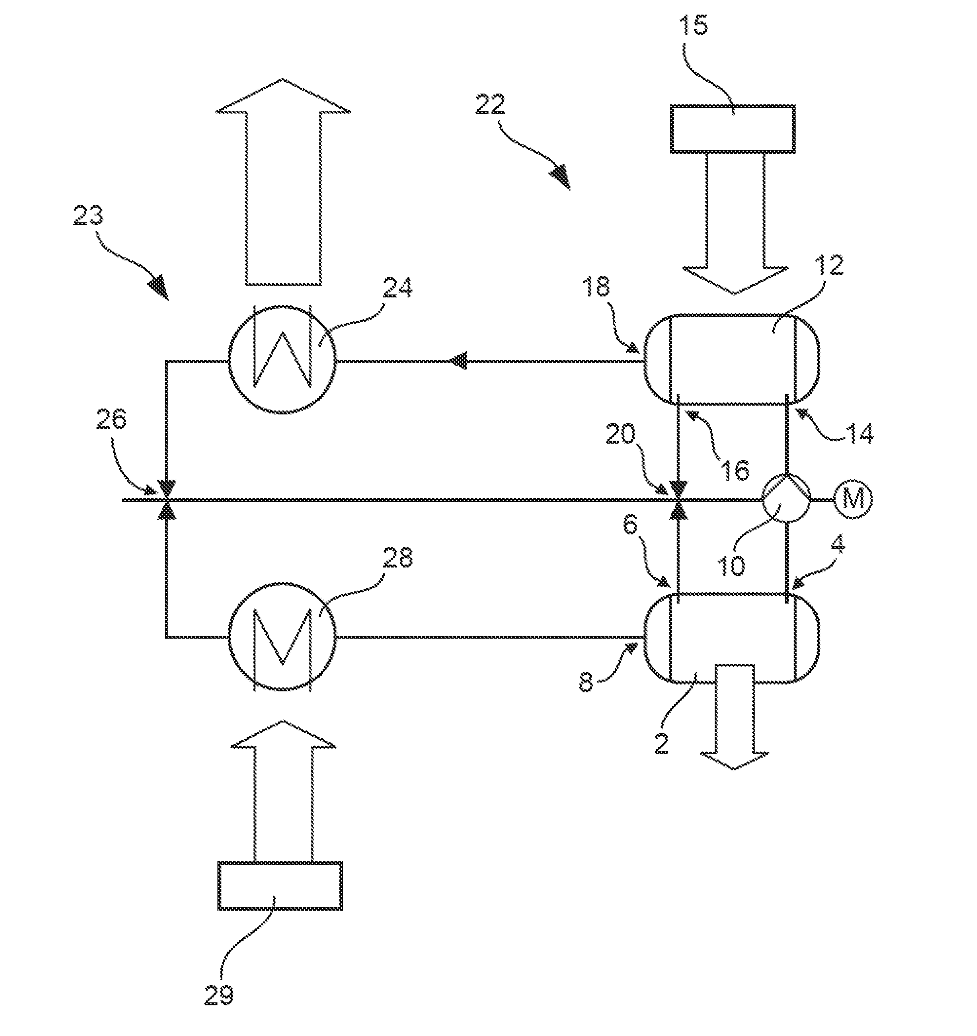
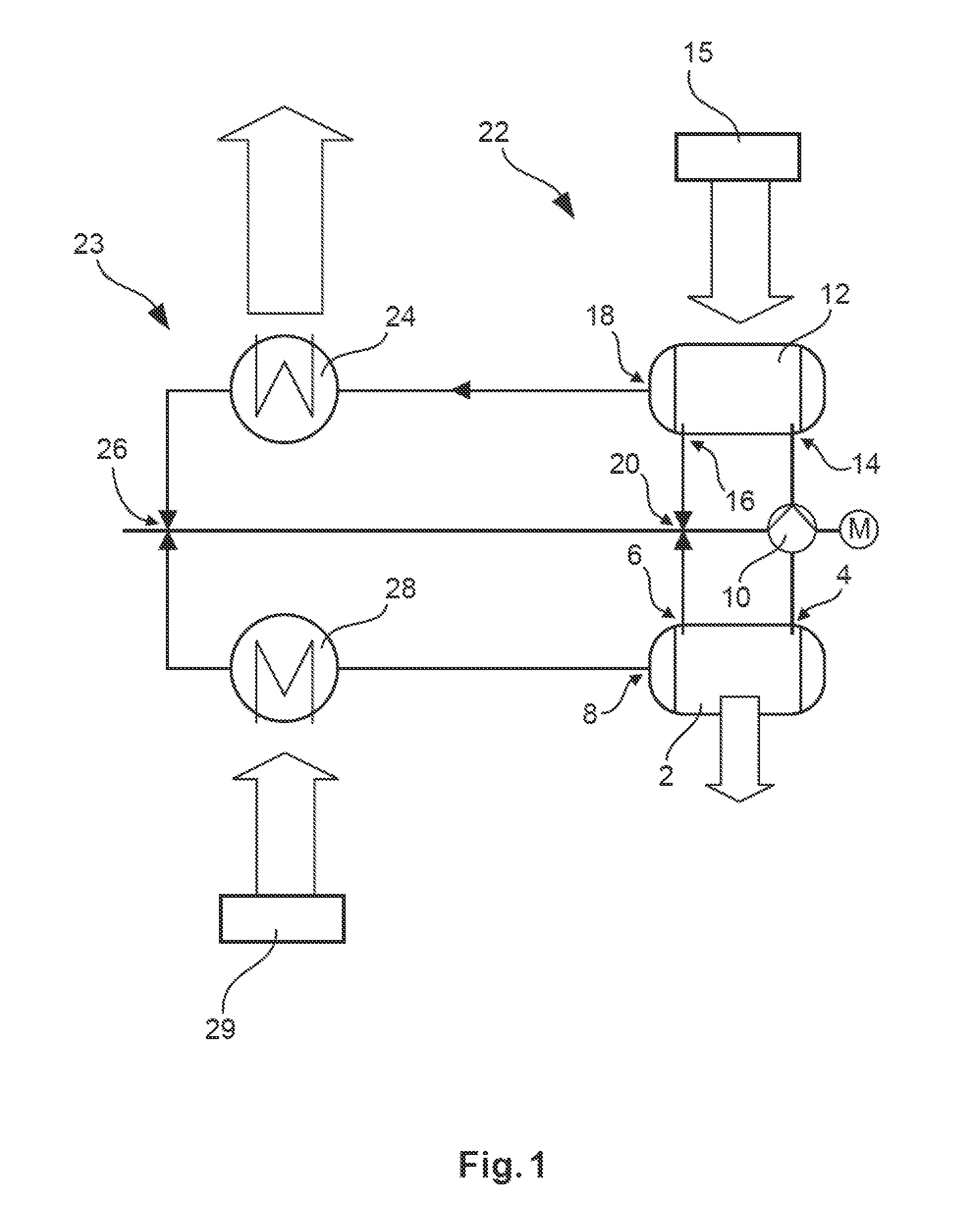
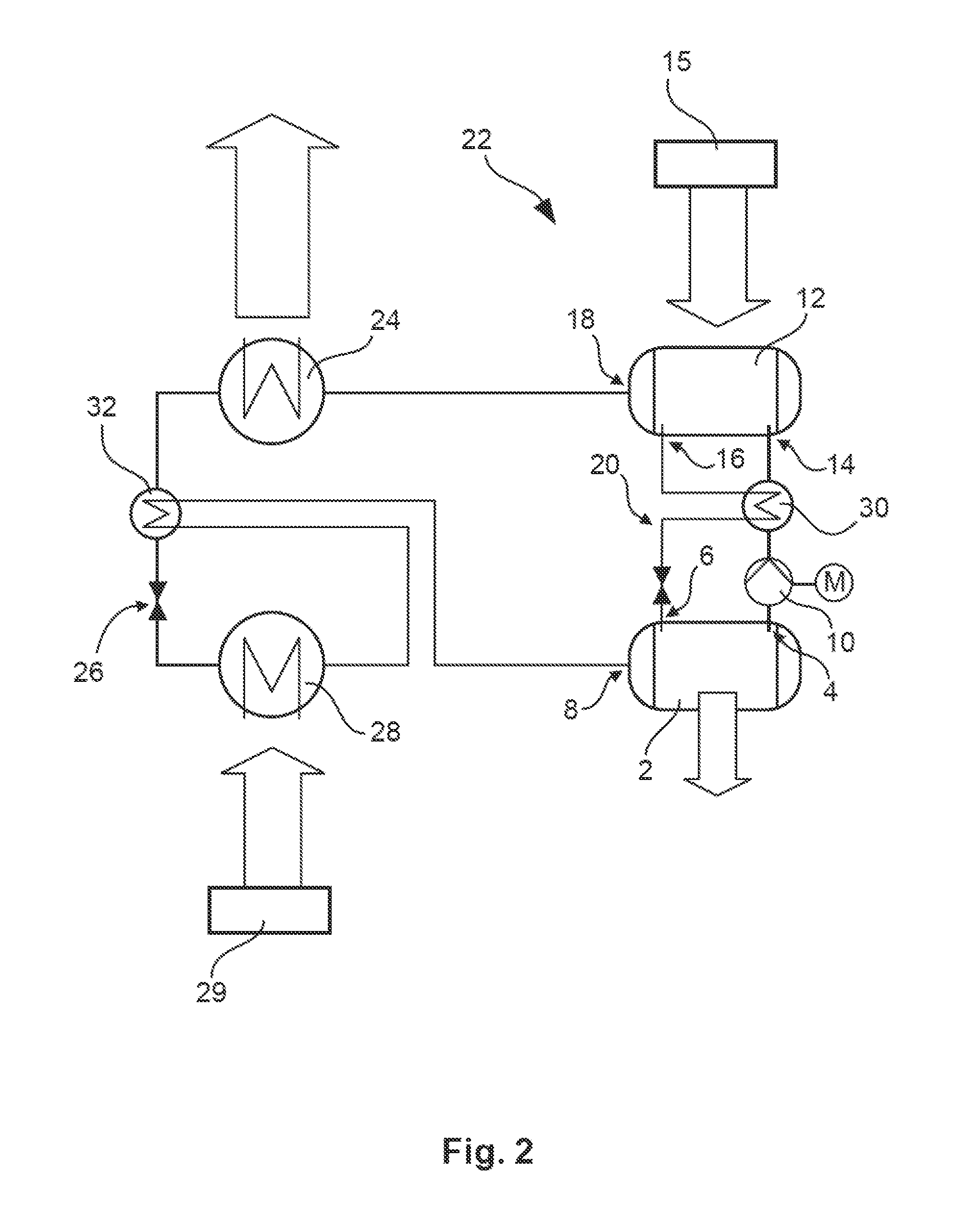
[0041]FIG. 1 shows a diagrammatic design of a cooling system in a vehicle in a simple embodiment. An absorber tank 2 comprises a liquid absorbent that may be implemented, for example, in the form of water. The absorber tank 2 comprises an absorber tank outlet 4 and an absorber tank inlet 6 as well as a steam inlet 8. From the absorber tank outlet 4 absorbent may be removed and conveyed to a regenerator tank 12 by way of an absorbent pump 10. The regenerator tank 12 comprises a regenerator tank inlet 14 and a regenerator tank outlet 16, as well as a steam outlet 18. By way of a first pressure reduction means 20, which is, for example, designed as a throttle valve, absorbent from the regenerator tank 12 may flow back to the absorber tank 2. Correspondingly, an absorbent circuit 22 is formed between the absorber tank 2 and the regenerator tank 12, which absorbent circuit 22 may also be referred to as a thermal compressor.

[0042]By way of its steam inlet 8 the absorber tank 2 is subjecte...


PUM


Abstract

A cooling system of a vehicle with a fuel cell includes an absorbent circuit with an absorber tank, a regenerator tank, an absorbent pump and a first pressure reduction means and a coolant circuit with a condenser connected to a steam outlet of the regenerator tank, a second pressure reduction means and an evaporator arranged between a steam inlet of the absorber tank and the second pressure reduction means. The regenerator tank is designed to desorb the coolant in solution in the absorbent by absorbing a first quantity of heat and to introduce it in a vaporous state into the condenser. The evaporator is designed to evaporate the coolant while absorbing a second quantity of heat and to introduce it in the vaporous state into the absorber tank. At least one of the first and of the second quantity of heat could be provided by the fuel cell.

Description

CROSS-REFERENCE TO RELATED APPLICATIONS[0001]This application claims the benefit of the filing date of U.S. Provisional Patent Application No. 61 / 561,348, filed Nov. 18, 2011, the disclosure of which is hereby incorporated herein by reference.TECHNICAL FIELD[0002]The invention relates to a vehicle with a cooling system and to a method for cooling in a vehicle.BACKGROUND OF THE INVENTION[0003]In vehicles and in particular in a commercial aircraft a host of cooling tasks are to be performed by cooling systems. Apart from cooling large quantities of air for cabin air conditioning, other heat-generating devices are also to be cooled, which devices relate, in particular, to electrical and electronic apparatus. Commonly-used air conditioning systems of a commercial aircraft are based on cooling units that implement an air circuit method (Joule-Thomson method) and / or an evaporator circuit method (Clausius-Rankine method). These circuits require the operation of compressors that are supplie...

Claims


Application Information

Patent Timeline
IPC IPC(8): F25B27/02
CPCB64D2013/0644B64D2013/0674B64D37/34B64D2041/005F25B27/02F25B15/04Y02E60/50B64D13/08Y02T90/36Y02T50/56H01M8/04029H01M8/04059H01M8/04074F25B25/02Y02T50/50Y02T90/40Y02A30/274
Inventor GREFE, MARCO
Owner AIRBUS OPERATIONS GMBH
Learn More