
Agile control model system and method

Active Publication Date: 2013-05-16
ROCKWELL AUTOMATION TECH
View PDF12 Cites 18 Cited by
  • Summary
  • Abstract
  • Description
  • Claims
  • Application Information

AI Technical Summary

Benefits of technology

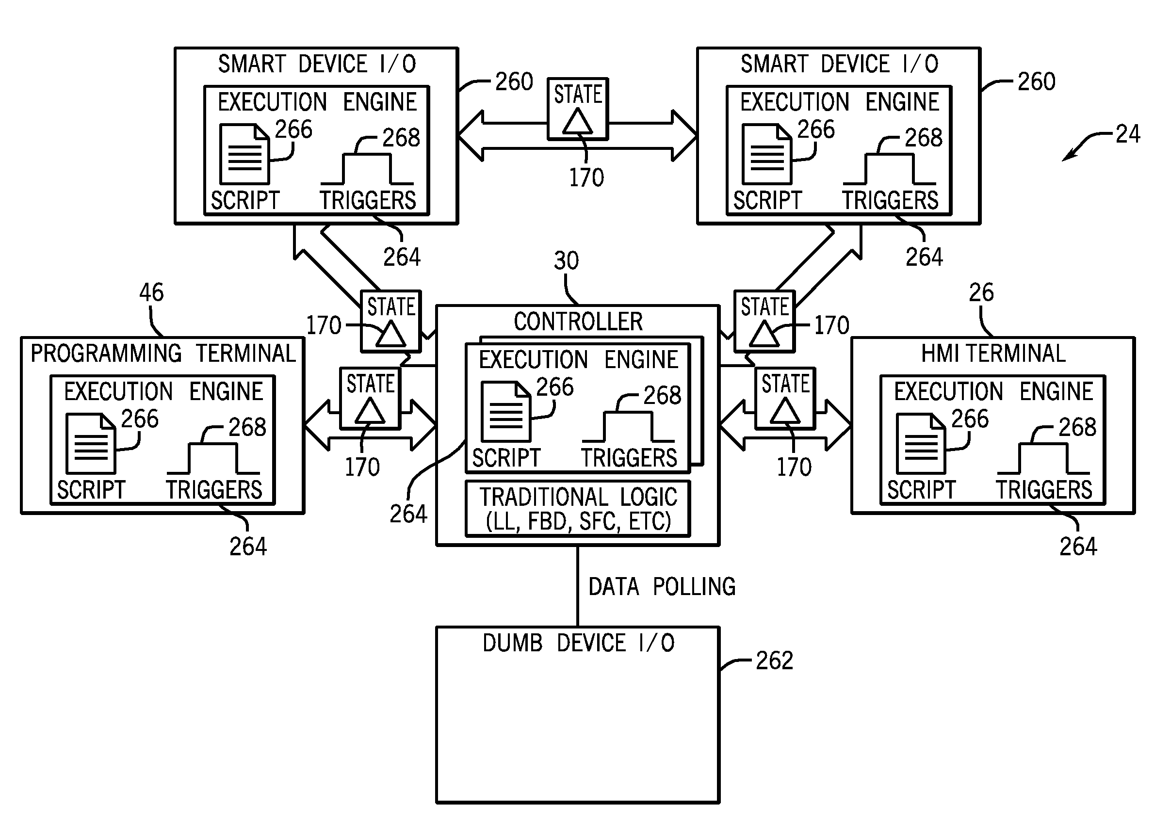
The present invention provides a way to communicate changes to objects in an automation control and monitoring system. Rather than sending all the data about a changed object, only the changed parts are sent. This reduces the amount of data transfer and makes the communication more efficient. When an object is deleted, only the information that it has been changed is sent. This is done by using a data-driven approach that doesn't require information about the full object. The changes are applied using execution engines embedded in different components of the system. This enables more efficient processing and takes advantage of multiple CPU cores.

Problems solved by technology

It is now recognized that such approaches are sometimes inefficient, providing more information than is necessary to describe a changed state of objects within the control and monitoring system.
Providing the entire state of an object may result in bandwidth inefficiencies in communicating the state data as well as processing inefficiencies in consuming and using the data.
Further, it is now recognized that such approaches of providing full state data may, in some cases, provide increased potential for inadvertent overwriting of other state changes provided in the control and monitoring system.
The reliance on centralized data models may result in processing inefficiencies and increased dependencies on components (e.g., a controller) hosting the centralized data models.

Method used


Image

  • Agile control model system and method
  • Agile control model system and method
  • Agile control model system and method

Examples


Embodiment Construction

[0025]Typically, control and monitoring systems have relied heavily on automation controllers such as programmable logic controllers (PLCs) and automation controller programming (e.g., PLC programming) to affect the control and monitoring systems when state changes are communicated. Automation controller programming relies heavily on event-based and / or schedule-based execution of tasks and / or logic (e.g., machine-readable instructions written in a programming language, such as relay ladder logic) to affect change in the control and monitoring system. The automation controllers are often used to consume all input data, calculate and distribute output data, process changes to the data, and distribute data to the components of the control and monitoring system. Unfortunately, such heavy reliance on a centralized data model hosted and affected by a component of the control and monitoring system (e.g., the automation controllers and automation controller programming) has provided several...


PUM


Abstract

A control and monitoring system is provided that includes an automation controller. The system includes a distributed model stored on the automation controller. Changes to the distributed model are provided via delta scripts that define only the changes to the model. Further, the control and monitoring system 24 includes distributed execution engines that execute commands based upon trigger events determined in the system. a plurality of automation control components networked together and with the automation controller, wherein the plurality of automation control components are capable of load balancing among the plurality of automation control components in response to performance demands of the control and monitoring system. These features of the control and monitoring system enable load balancing, data and processing redundancy, and collaborative design within the control and monitoring system.

Description

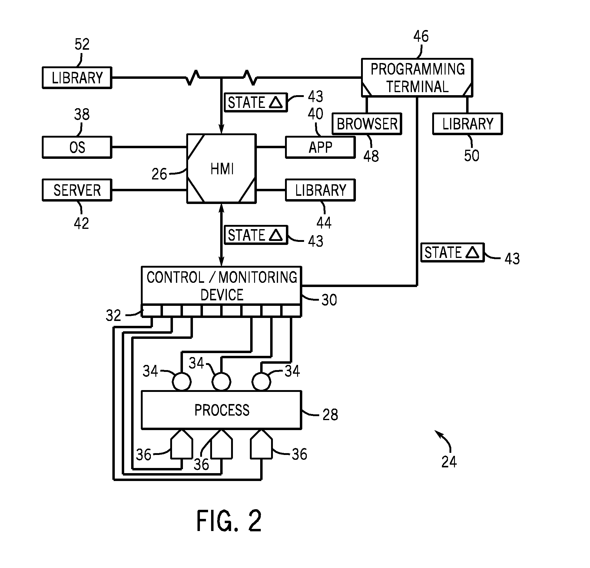
[0001]This application is a Non-Provisional of U.S. Provisional Patent Application No. 61 / 559,008, entitled “Extensible Control Model System and Method,” filed Nov. 11, 2011, which is herein incorporated by reference.BACKGROUND[0002]Embodiments of the present disclosure relate generally to the field of automation control and monitoring systems. More particularly, embodiments of the present disclosure relate to techniques for dynamic and adaptable automation control.[0003]A wide range of applications exist for automation control and monitoring systems, particularly in industrial settings. Such applications may include the powering of a wide range of actuators, such as valves, electric motors, and so forth, and the collection of data via sensors. Typical automation control and monitoring systems may include one or more components, such as: programming terminals, automation controllers, input / output (I / O) modules, and / or human-machine interface (HMI) terminals.[0004]The human machine i...

Claims


Application Information

Patent Timeline
IPC IPC(8): G05B11/01
CPCG05B19/054G05B2219/25057G05B19/41845G06F9/52Y02P90/02
Inventor GOVINDARAJ, SUBBIANBRONIKOWSKI, JOSEPHKALAN, MICHAELKOWAL, STEVEN JOHNJASPER, TARYLPLACHE, KENNETHREICHARD, DOUGLAS J.REID, DOUGLAS W.RISCHAR, CHARLES
Owner ROCKWELL AUTOMATION TECH
Learn More