
Image information acquiring apparatus, image information acquiring method and image information acquiring program

a technology of image information and acquisition apparatus, applied in the field of image information acquisition apparatus, image information acquisition method and image information acquisition program, can solve the problems of difficult to realize in practice a device that satisfies these assumptions, and increasing the size and the number of elements. , to achieve the effect of fewer artifacts

Active Publication Date: 2013-05-09
CANON KK
View PDF10 Cites 9 Cited by
  • Summary
  • Abstract
  • Description
  • Claims
  • Application Information

AI Technical Summary

Benefits of technology

The present invention is about improving the quality of reconstructed image data that can be obtained from an acoustic wave detector on a flat plate. This invention reduces the number of artifacts that can occur when detecting acoustic waves.

Problems solved by technology

It is not easy to realize in practice a device that satisfies these assumptions.
In an actual object, for instance, it is difficult to obtain acoustic wave detection information over the entirety of a closed space surface that surrounds the whole object.
Also, increasing the size of the acoustic wave measurement region requires increasing the size and the number of elements of the acoustic detector, and increasing the signal processing and control burden of each element, all of which translates into greater manufacturing costs.

Method used


Image

  • Image information acquiring apparatus, image information acquiring method and image information acquiring program
  • Image information acquiring apparatus, image information acquiring method and image information acquiring program
  • Image information acquiring apparatus, image information acquiring method and image information acquiring program

Examples


example 1

[0062]The image information acquiring apparatus of the present embodiment is a photoacoustic diagnostic apparatus that detects acoustic waves generated through irradiation of light, and that generates three-dimensional reconstructed image data on the basis of information relating to the detected acoustic waves.

[0063](Device Configuration)

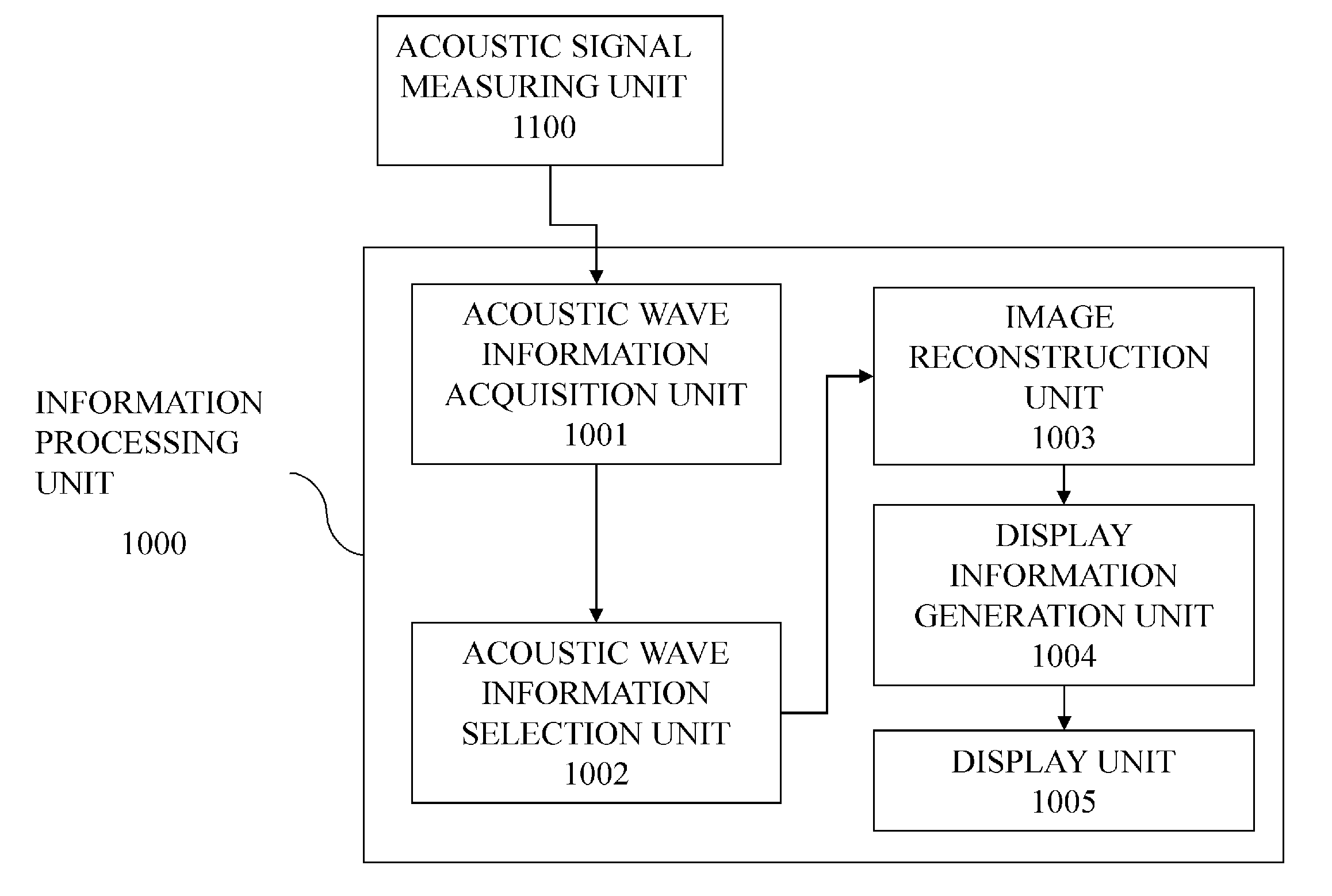
[0064]FIG. 1 is a block diagram illustrating the functional configuration of a photoacoustic diagnostic apparatus according to the present example. As illustrated in FIG. 1, the photoacoustic diagnostic apparatus according to the present example comprises an information processing unit 1000 and an acoustic signal measuring unit 1100. As explained in detail below, the acoustic signal measuring unit 1100 transmits, to the information processing unit 1000, acoustic signal information and information relating to the position of elements on a reception surface of an acoustic wave detector 1105 (FIG. 3). The acoustic wave detector 1105 is, for instance, a...

example 2

[0114]In the image information acquiring apparatus according to Example 1 an example of a three-dimensional image reconstruction process has been explained in which the reconstruction area is an area above a reception surface of an acoustic wave detector, and in which there is used acoustic signal information of elements selected from among elements on the reception surface of the acoustic wave detector. In the present example, unlike in Example 1, the acoustic wave detector is moved, and a reception area is a combination of the reception surface at each position. Herein, a three-dimensional image reconstruction process is carried out in which the reconstruction area is an area above the reception area, using acoustic signal information of elements selected from among elements at each position within the reception area.

[0115]Specifically, there is generated acoustic signal information and an element on the reception area that are handled as equivalent to acoustic signal information ...


PUM


Abstract

An image information acquiring apparatus of the present invention includes an acoustic wave detector having, disposed on a reception surface thereof, a plurality of elements that detect acoustic waves generated by an object corresponding to a reconstruction area; an acoustic signal generator that generates acoustic signals that are used in image reconstruction, from the detected acoustic waves; an element selector that selects elements that are used in image reconstruction; and a reconstructor that performs image reconstruction of a point of interest using acoustic signals based on the acoustic waves detected by the selected elements, the image information acquiring apparatus being configured such that, for each selected element, there exists another selected element located at a symmetrical position with respect to a point at which the reception surface is intersected by a perpendicular line drawn from the point of interest to the reception surface.

Description

TECHNICAL FIELD[0001]The present invention relates to an image information acquiring apparatus, an image information acquiring method and an image information acquiring program.BACKGROUND ART[0002]Ongoing active research is being carried out, in medical fields, on optical imaging devices for obtaining information of the interior of objects such as living bodies using light irradiated from a light source, for instance a laser. Photoacoustic Tomography (PAT) is one such optical imaging technique. Photoacoustic tomography is a technique wherein information associated with values of optical characteristics in the interior of the object can be visualized on the basis of acoustic waves generated by biological tissue, on account of the photoacoustic effect, upon absorption of energy from light that propagates or diffuses through the interior of the object. The information associated with the optical characteristic values is obtained by detecting acoustic waves at a plurality of sites that ...

Claims


Application Information

Patent Timeline
Patent Type & Authority Applications(United States)
IPC IPC(8): G06K9/32
CPCA61B5/0095A61B8/15G06K9/3233A61B2562/046G10K15/046A61B2562/0204G06V10/25
Inventor WANDA, KOICHIRO
Owner CANON KK
Learn More