
Energy substraction method and apparatus

a technology of energy subtraction and energy subtraction, which is applied in the field of energy subtraction methods and energy subtraction apparatuses, can solve the problems of user time and effort in specifying proper parameters for each application part and the physical frame of the patient, complicated whole apparatus configuration and cost, and achieve the effect of less motion artifacts

Active Publication Date: 2009-11-19
FUJIFILM CORP
View PDF13 Cites 11 Cited by
  • Summary
  • Abstract
  • Description
  • Claims
  • Application Information

AI Technical Summary

Benefits of technology

[0016]It is therefore an object of the present invention to resolve the above-described problems and to provide an energy subtraction method and an energy subtraction apparatus enabling, in performing energy subtraction processes on various parts, acquisition of images with less artifacts regardless of information of body parts of a subject or movements of the body parts.
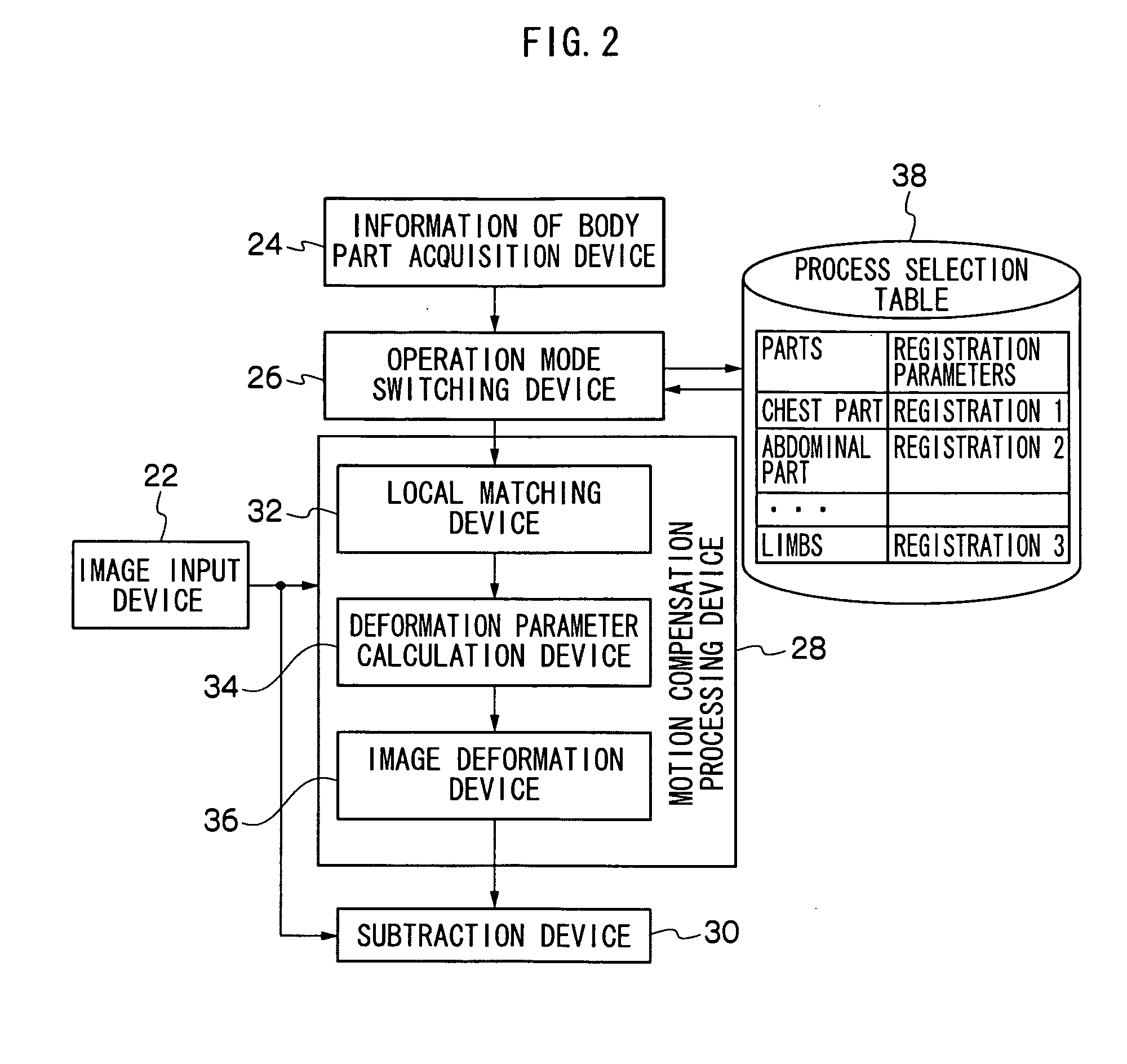
[0017]A first aspect of the present invention provides an energy subtraction apparatus which can accomplish the above-mentioned object, the energy subtraction apparatus comprising: an image input device which inputs two or more different kinds of radiographic images having been taken by irradiating a subject with radiation rays with different radiation qualities; an information of body part acquisition device which acquires a information of body part; a motion compensation processing device which compensates for movement of the subject between the two or more different kinds of radiographic images; a subtraction device which performs an energy subtraction process on the two or more different kinds of radiographic images; and an operation mode switching device which switches an operation mode of the motion compensation processing device depending on the information of body part.
[0022]Thus, since it is arranged such that the registration parameters can also be switched depending on the information of body part, registration that can follow the movement of the part is made possible, and therefore images with less motion artifacts can be acquired regardless of information of body parts.
[0024]Thus, since it is arranged such that the way of image deforming can be switched depending on the information of body part, registration that can follow the movement of the part is made possible, and therefore images with less motion artifacts can be acquired regardless of information of body parts.
[0031]Thus, since it is arranged such that the registration parameters can also be switched depending on the information of body part, registration that can follow the movement of the part is made possible, and therefore images with less motion artifacts can be acquired regardless of information of body parts.
[0033]Thus, since it is arranged such that the way of image deforming can be switched depending on the information of body part, registration that can follow the movement of the part is made possible, and therefore images with less motion artifacts can be acquired regardless of information of body parts.

Problems solved by technology

However, with respect to the artifact reduction method using cardiac synchronization as disclosed in the above-mentioned Japanese Patent Application Laid-Open No. 2002-325756, there is a problem in that the method requires an apparatus for electrocardiographic monitoring which makes the whole apparatus configuration complicated and costing.
Moreover, there is another problem in that a delay of about 150 msec can be caused between the electrocardiographic motion and the actual cardiac motion.
In addition, with respect to the artifact reduction method using image processing as disclosed in the above-mentioned Japanese Patent Application Laid-Open No. 2003-244542, there is a problem in that parameters such as intervals among the control points, a template size, etc. are to be determined by a user, which means that the user is required to spend time and effort in specifying proper parameters for each application part and physical frame of the patient.
Furthermore, although the method of combining local matching and nonlinear transformation may be effective with respect to the chest part such as a heart that exhibits local motions, it may be troublesome with respect to other parts with less local motions because it may increase the number of calculations to be done which may turn out unnecessary.

Method used


Image

  • Energy substraction method and apparatus
  • Energy substraction method and apparatus
  • Energy substraction method and apparatus

Examples


Embodiment Construction

[0041]Now with reference to the attached drawings, an energy subtraction method and an energy subtraction apparatus according to the present invention will be described in detail.

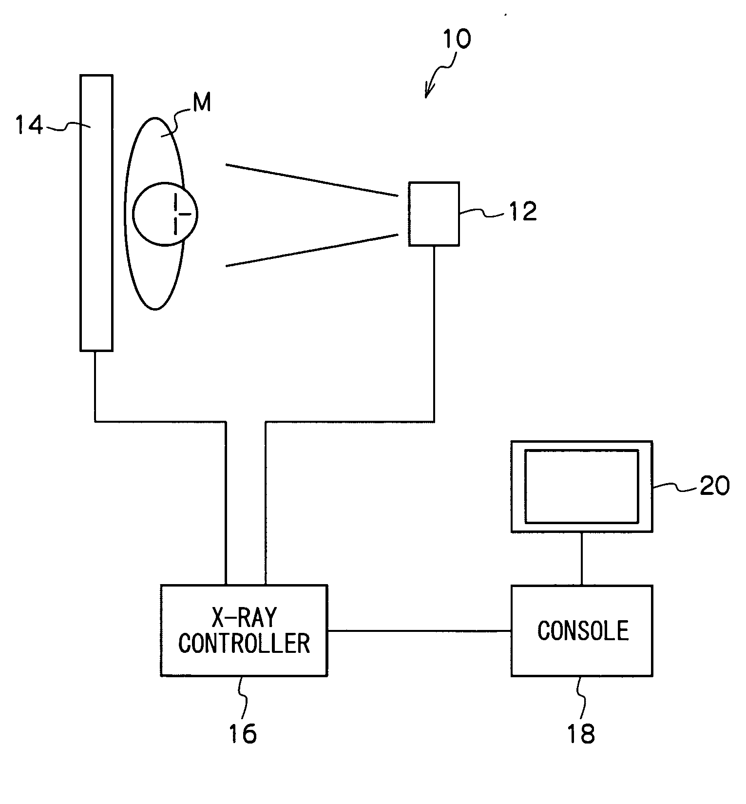
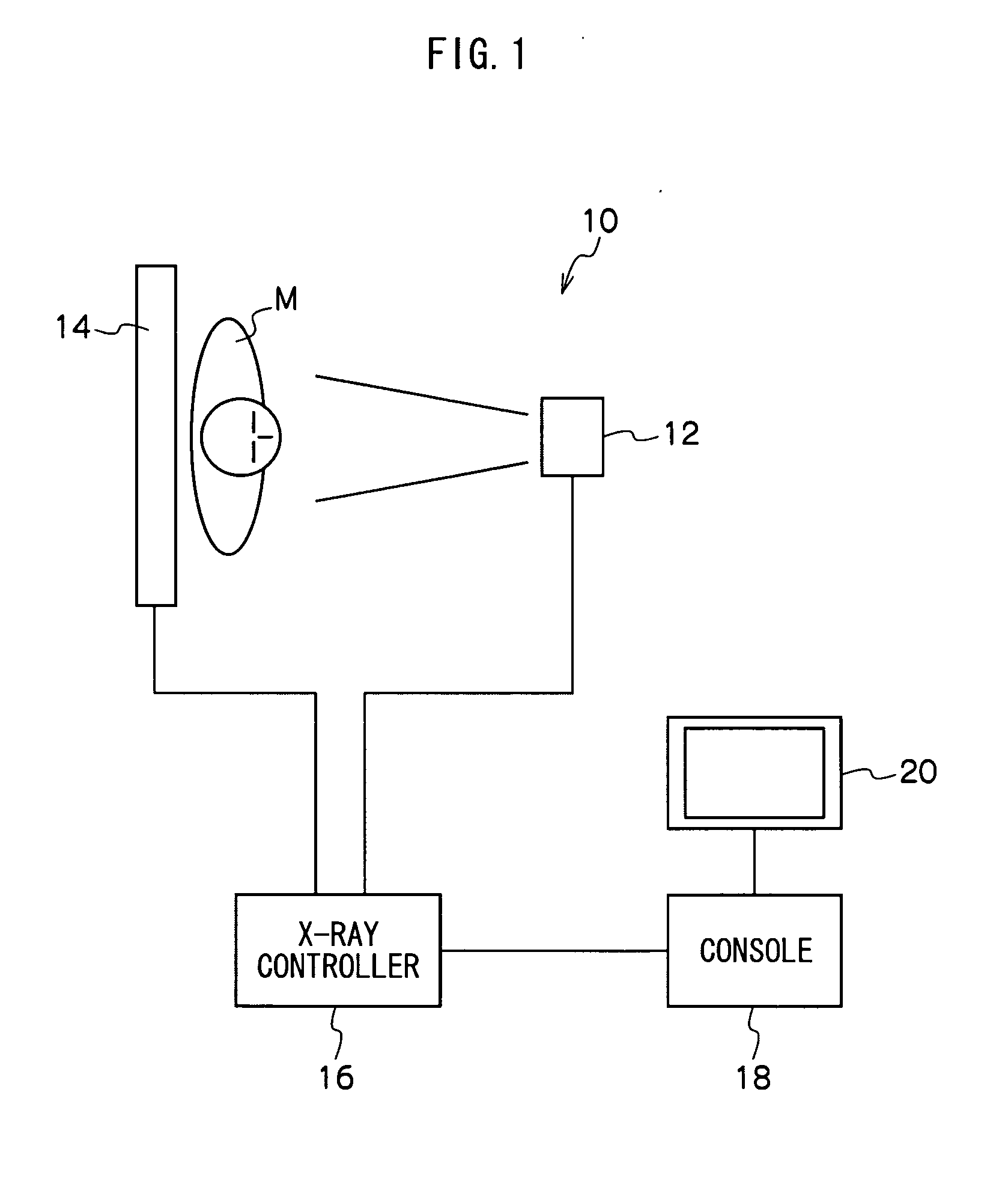
[0042]FIG. 1 is a schematic configuration diagram showing one embodiment of the energy subtraction apparatus which implements the energy subtraction method according to the present invention.

[0043]The energy subtraction apparatus according to the present embodiment configures an X-ray imaging system that uses a flat panel X-ray detector (FPD).

[0044]As shown in FIG. 1, an energy subtraction apparatus 10 according to the present embodiment is configured as mainly including an X-ray source 12 which irradiates a subject M with X-ray, a flat panel X-ray detector (FPD) 14 which detects the X-ray having penetrated through the subject M to output the detected result as a detection signal, an X-ray controller 16, and a console 18. The console 18 is connected with a display 20 of which screen takes a form of a touch ...


PUM


Abstract

The energy subtraction apparatus of the present invention comprises an image input device which inputs two or more different kinds of radiographic images having been taken by irradiating a subject with radiation rays with different radiation qualities, an information of body part acquisition device which designates a information of body part, a motion compensation processing device which performs a registration process by compensating for shift between corresponding points between the two or more different kinds of radiographic images due to movement of the subject, a subtraction device which performs an energy subtraction process on the two or more different kinds of radiographic images, and an operation mode switching device which switches an operation mode of the registration process at the motion compensation processing device depending on the information of body part.

Description

BACKGROUND OF THE INVENTION[0001]1. Field of the Invention[0002]The present invention relates to an energy subtraction method and an energy subtraction apparatus, and in particular, relates to a technique for applying a method of acquiring energy subtraction images by taking at least two or more kinds of radiographic images at different radiation energy levels to radiography of various parts.[0003]2. Description of the Related Art[0004]Conventionally, there is an energy subtraction technology known as a kind of technology with which radiations with different energy distributions are applied to one and the same subject to shoot at least two or more kinds of radiographic images at different radiation energy levels, and then the radiographic images are taken as digital image signals to have respective pixels matched between the respective images and weighted to go through a subtraction process, whereby images exhibiting distributions of substances with particular radiation absorption c...

Claims


Application Information

Patent Timeline
IPC IPC(8): H05G1/64G06K9/00
CPCG06K9/6206G06K2209/05G06T5/50G06T2207/20224G06T2207/10116G06T2207/20021G06T2207/30008G06T7/0026G06T7/32G06V10/754G06V2201/03
Inventor AKAHORI, SADATO
Owner FUJIFILM CORP
Learn More