
Multi-axle joint shifting loading apparatus for processing center and detection method for static stiffness distribution

a technology of static stiffness distribution and loading apparatus, which is applied in the direction of structural/machine measurement, instruments, manufacturing tools, etc., can solve the problems of cutting load not being fully simulated at the main axle side, and the inability to detect static stiffness distribution

Active Publication Date: 2013-05-09
XIAN UNIV OF TECH
View PDF9 Cites 33 Cited by
  • Summary
  • Abstract
  • Description
  • Claims
  • Application Information

AI Technical Summary

Benefits of technology

The present invention can apply full loads for simulation, detect the static stiffness distribution of a processing center by changing the loading position through a multi-axle joint movement, and design various processing surface shapes of load-receiving tests by adjusting the direction of the ball socket axis of the load-exerting component. This allows for the satisfaction of experimental requirements for different ratios of simulation loads and different numbers of joint axles.

Problems solved by technology

The processing center static stiffness detection apparatus and the detecting method available both in China and abroad can only detect the static stiffness at one determined position, and cannot detect the static stiffness distribution.
The processing center static stiffness detection apparatuses and detecting methods both in China and abroad cannot apply six simulation loads to the main axle.
Therefore the cutting load cannot be fully simulated at the main axle side.

Method used


Image

  • Multi-axle joint shifting loading apparatus for processing center and detection method for static stiffness distribution
  • Multi-axle joint shifting loading apparatus for processing center and detection method for static stiffness distribution
  • Multi-axle joint shifting loading apparatus for processing center and detection method for static stiffness distribution

Examples


embodiment 1

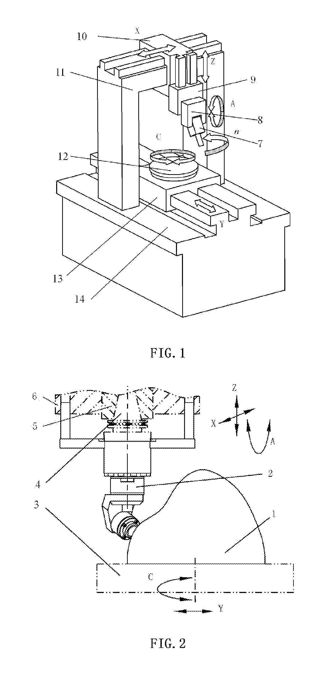
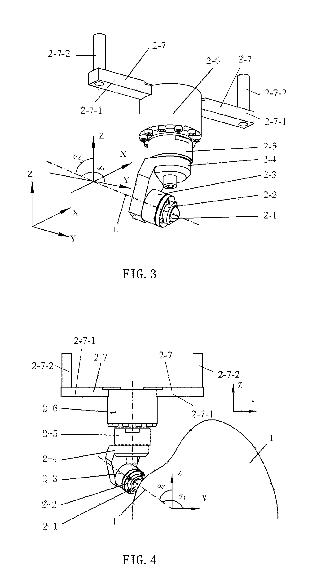
[0030]When the shifting loading apparatus according to the present invention is used in a 5-axle joint upright processing center or a horizontal processing center, the method for detecting the processing center static stiffness distribution is as follows: as shown in FIGS. 2 and 4, firstly the connection component A 2-6 of the load-exerting component 2 is fixedly connecting with the tool shank 4, wherein the tool shank 4 is tensioned in the taper hole in the main axle 5, and the connection component B 2-7 disposed on the connection component A 2-6 is connected with the main axle housing 6 through the vertical bar 2-7-2; the load-receiving test piece 1 is mounted on the worktable 3; a displacement sensor is mounted, which may be installed in plural, for example, on the main axle 5, the main axle housing 6 and the worktable 3; then the load-exerting component 2 and the load-receiving test piece 1 are moved to a preset first loading position through a joint movement of Z axle, Y axle, ...

embodiment 2

[0031]When the shifting loading apparatus according to the present invention is used in a 5-axle joint turning-milling composite processing center, the method differs from the first embodiment in that a position function is utilized when the main axle performs a turning cutting, and thus the connection component B 2-7 is not required, wherein the multi-axle joint shifting loading apparatus is illustrated in FIG. 5, as long as the connection component A 2-6 and the tool shank 4 are fixedly connected, the tool shank 4 is tensioned in a taper hole in the main axle 5, and the load-receiving test piece 1 is mounted on the worktable 3, the detection method can be performed. In this case, the method for detecting the static stiffness distribution of the processing center is the same as that of the first embodiment, that is to say, the method also change the loading position through a joint movement of Z axle, Y axle, X axle, C axle and A axle, the detailed description of which is omitted h...

embodiment 3

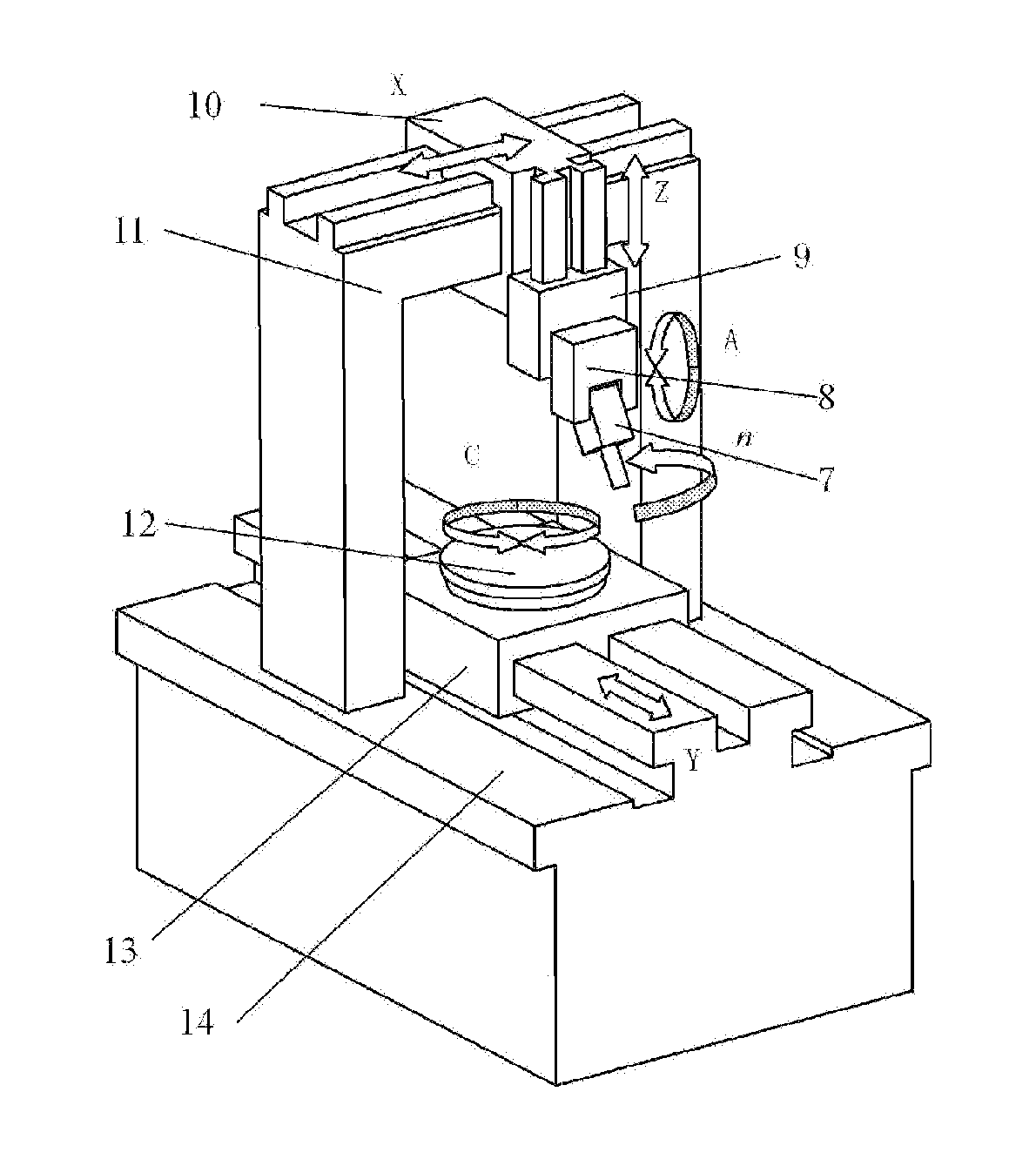
[0032]When the shifting loading apparatus according to the present invention is used in a 4-axle joint processing center having X axle, Y axle, Z axle and C axle (that is, the processing center shown in FIG. 1 has no A axle), the load exerting component 2 is connected to the processing center in the same manner of the first embodiment with a difference that the loading position is changed through a joint movement of X axle, Y axle, Z axle and C axle. The shape of the load-receiving surface of the load-receiving test piece 1 can be designed in a rather simple manner.

[0033]Among the axles, a slewing axle, an axis of which is parallel with X axle is called as A axle; and a slewing axle, an axis of which is parallel with Y axle is called as B axle, and a slewing axle, an axis of which is parallel with Z axle is called as C axle.


PUM

PropertyMeasurementUnit
cylindrical shapeaaaaaaaaaa
shapeaaaaaaaaaa
static stiffness distributionaaaaaaaaaa

Abstract

Disclosed is a processing center multi-axis joint deflection loading apparatus comprising a load-receiving test piece and a load-exerting component. The load-exerting component is constituted by a steel ball, a cap, a ball socket, a bent board, a force sensor, a connection component A, and a connection component B. The connection component A is fixedly connected to a blade handle of the processing center; the blade handle is pulled tight within a bored hole on a main axle; and the connection component A is connected to a main housing via the connection component B. In a method using the apparatus for an inspection of static stiffness distribution, by means of a multi-axle joint movement, moving the load-exerting component and the load-receiving test piece to a preset loading position, allowing the normal at a load-receiving point on a load-receiving face of the load-receiving piece to be aligned with the axis of the ball socket; with the amount of shift measured by position-shift sensors fitted on the main axle, the main axle housing, and a working platform, and the amount of simulated load measured by the force sensor of the loaded-exerting component, deriving a stiffness measurement of the load-exertion position under a simulated load; changing the load-exertion position by means of a multi-axle joint movement, repeating in sequence the previous steps, thus deriving a stiffness distribution under the simulated load.

Description

TECHNICAL FIELD[0001]The present invention belongs to a detection technology for simulating static stiffness of numerical controlling machine tools under loads at different positions in a working space, and more particularly relates to a multi-axle joint shifting loading apparatus for a processing center and a detection method for a static stiffness distribution.BACKGROUND ART[0002]In a working space of a machine tool, the magnitude of loads (including force and moment) and loading positions of members of the machine tool vary as the position of the machining point varies, so that a static stiffness distribution of the machine tool changes. The change in static stiffness at different machining positions may be described by a stiffness distribution. The magnitude of the static stiffness and the static stiffness distribution influence the machining precision directly (especially the stiffness distribution influences the shape precision of the machining surface directly), and influence...

Claims


Application Information

Patent Timeline
Patent Type & Authority Applications(United States)
IPC IPC(8): G01N3/40G01M99/00
CPCG01M99/007B23Q2230/002B23Q17/00G01N3/40
Inventor HUANG, YUMEIYANG, XINGANGHUI, YEZHAO, RUI
Owner XIAN UNIV OF TECH
Learn More