Ink reduction method

Active Publication Date: 2013-04-25
EASTMAN KODAK CO
View PDF22 Cites 14 Cited by
  • Summary
  • Abstract
  • Description
  • Claims
  • Application Information

AI Technical Summary

Benefits of technology

This patent aims to create a system that can reduce the amount of ink used in printing while maintaining high-quality images. By minimizing concavities in color gamut, the system can achieve significant reductions in both the average and maximum amounts of ink. This can help reduce ink costs and minimize negative effects on paper, such as wrinkling.

Problems solved by technology

However, a disadvantage is that the volume of the color gamut can often be greatly reduced, particularly in the region extending from saturated primaries (CMY) and secondaries (RGB) to the black point of the color gamut (i.e., the darkest color that can be printed given the ink load restrictions imposed).
Another disadvantage is that the color reproduction accuracy may be sacrificed when utilizing a device coordinate transform based approach rather than a colorimetric approach.
However, this approach does not address the problem that is encountered when attempting to keep the total ink below a designated TAC level when all colorimetric solutions on the locus of colorant values are above that TAC limit.

Method used


Image

  • Ink reduction method
  • Ink reduction method
  • Ink reduction method

Examples


second embodiment

[0076]FIG. 6B shows additional details for the create inverse transform step 415 according to a In this embodiment, the colorant load limit 325 is used as a constraint on the average colorant load, specifying a maximum average colorant load that can be printed given an input color distribution 665. This reflects the fact that often the factors that make it necessary to limit the colorant load are more a function of the average amount of colorant deposited across the printed image rather than the maximum colorant load that is produced for specific input color values. For example, wrinkle artifacts or smear artifacts can be produced on continuous inkjet printing systems if the average colorant load is too high even if no image artifacts are produced for local image regions having a high colorant load. In this case, the average colorant load limit will generally be a function of the type of receiver (e.g., paper) used in the color printing system. In other cases, the specification of ...

third embodiment

[0100]FIG. 6C shows additional details for the create inverse transform step 415 according to a In this embodiment, the colorant load limit 325 is used as a TAC limit as in the embodiment of FIG. 6A, specifying a maximum total colorant load that can be printed for any input color.

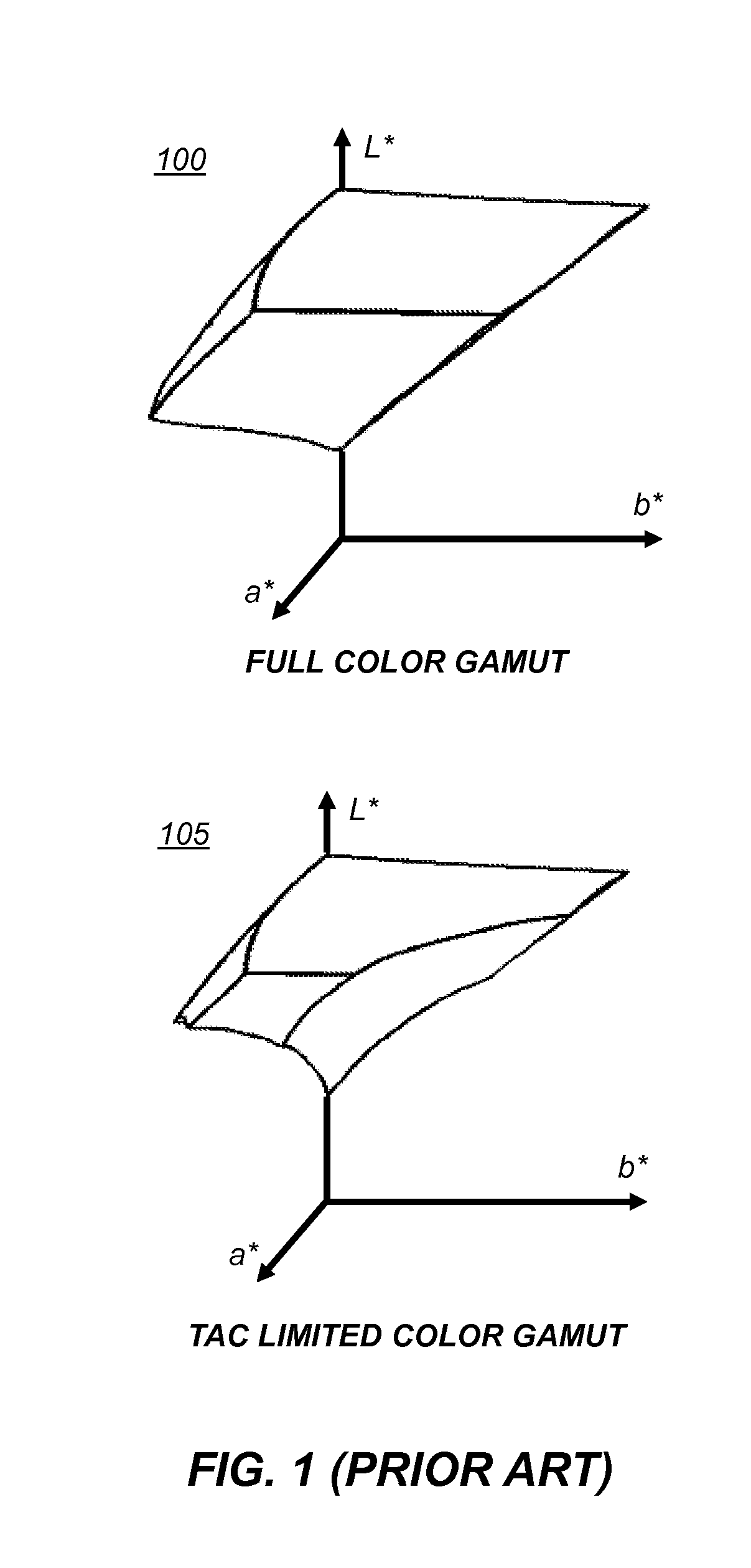
[0101]As discussed earlier, the imposition of a very low TAC limit can result in severely concave TAC-limited gamuts as shown in FIG. 7A, which can result in objectionable image artifacts. In order to avoid these artifacts, the embodiment shown in FIG. 6C uses a transformation function 705 to transform the native printing system model 410. In some embodiments, the transformation function 705 limits the maximum native colorant control values (e.g., C″M″Y″K″) that are used to print input images. For example, FIG. 8 shows plots of a series of transformation functions 705 where the native colorant control values are modified using scale factors to impose a series of maximum native colorant control value. In th...


PUM


Abstract

A method for forming a color transform for a color printing device having a plurality of colorant channels that includes applying a tone scale adjustment function and a total colorant load limit. An optimization process is used to optimize a merit function including a tone scale reproduction accuracy term and a gamut shape term. The method involves determining an initial merit function value responsive to an initial total colorant load limit and an initial set of tone scale adjustment parameters for a tone scale adjustment function. Modified tone scale adjustment parameters and a modified total colorant load limit are determined that provide an improved merit function value subject to a constraint that an average total colorant load is no more than a predefined threshold for a predefined distribution of input colors.

Description

CROSS-REFERENCE TO RELATED APPLICATIONS[0001]Reference is made to commonly assigned, co-pending U.S. patent application Ser. No. ______ (Docket K000677), entitled: “Improved method of ink reduction”, by Fischer et al., which is incorporated herein by reference.FIELD OF THE INVENTION[0002]The invention relates to color imaging, and more particularly, to ink reduction techniques for color printing devices.BACKGROUND OF THE INVENTION[0003]Ink optimization and total ink reduction has become an important new feature in various color management systems. For example, at the recent 2010 Technical Conference for the IDEAlliance / IPA, several ink-optimizing products were compared (see Sharma et al., “IPA Ink Optimization RoundUP 2010,” white paper presented at the 2010 IDEAlliance / IPA Technical Conference). These products attempt to reduce the amount of CMYK ink with little or no loss in color reproduction accuracy. Hence, these products were compared both in terms of the amount of ink reducti...

Claims


Application Information

Patent Timeline
IPC IPC(8): H04N1/60
CPCH04N1/6061H04N1/603
Inventor FISCHER, TIMOTHY A.EDGE, CHRISTOPHER J.
Owner EASTMAN KODAK CO
Why Eureka
Try Eureka