Melt container

a technology of container and smelt, which is applied in the field of smelt containers, can solve the problems of large economic loss, damage to the iron crust, and problem of melt leaching out, and achieve the effect of preventing the contamination of the smelt of impurities and suppressing the penetration of the smel

Inactive Publication Date: 2013-04-18
JNC CORP +2
View PDF3 Cites 0 Cited by
  • Summary
  • Abstract
  • Description
  • Claims
  • Application Information

AI Technical Summary

Benefits of technology

[0035]A melt container of the invention allows keeping a small amount of heat radiation of a melt, suppressing penetration of the melt and development of breakage or cracking to the minimum, holding the melt suitably, and also preventing the melt from impurity contamination.

Problems solved by technology

Thus, the iron crust is damaged, and in a serious case, a problem of the melt leaching out occurs.
From an operational aspect, such a case decreases production efficiency and also causes a large economic loss.
However, any research has not been conducted on a lining structure in consideration of densification, heat insulation and thermal conductivity of members that constitute the container in the melt containers described in the literatures, and the melt container has admitted of room for further improvement.
Until now, any melt container that allows suppressing penetration of the melt and development of breakage or cracking and further preventing the melt from impurity contamination has not been developed.
In particular, any research has not been conducted on members for constituting the container for holding the melt of zinc chloride or the mixed melt of the zinc chloride and zinc as described above.

Method used


Image

  • Melt container
  • Melt container

Examples


example 1

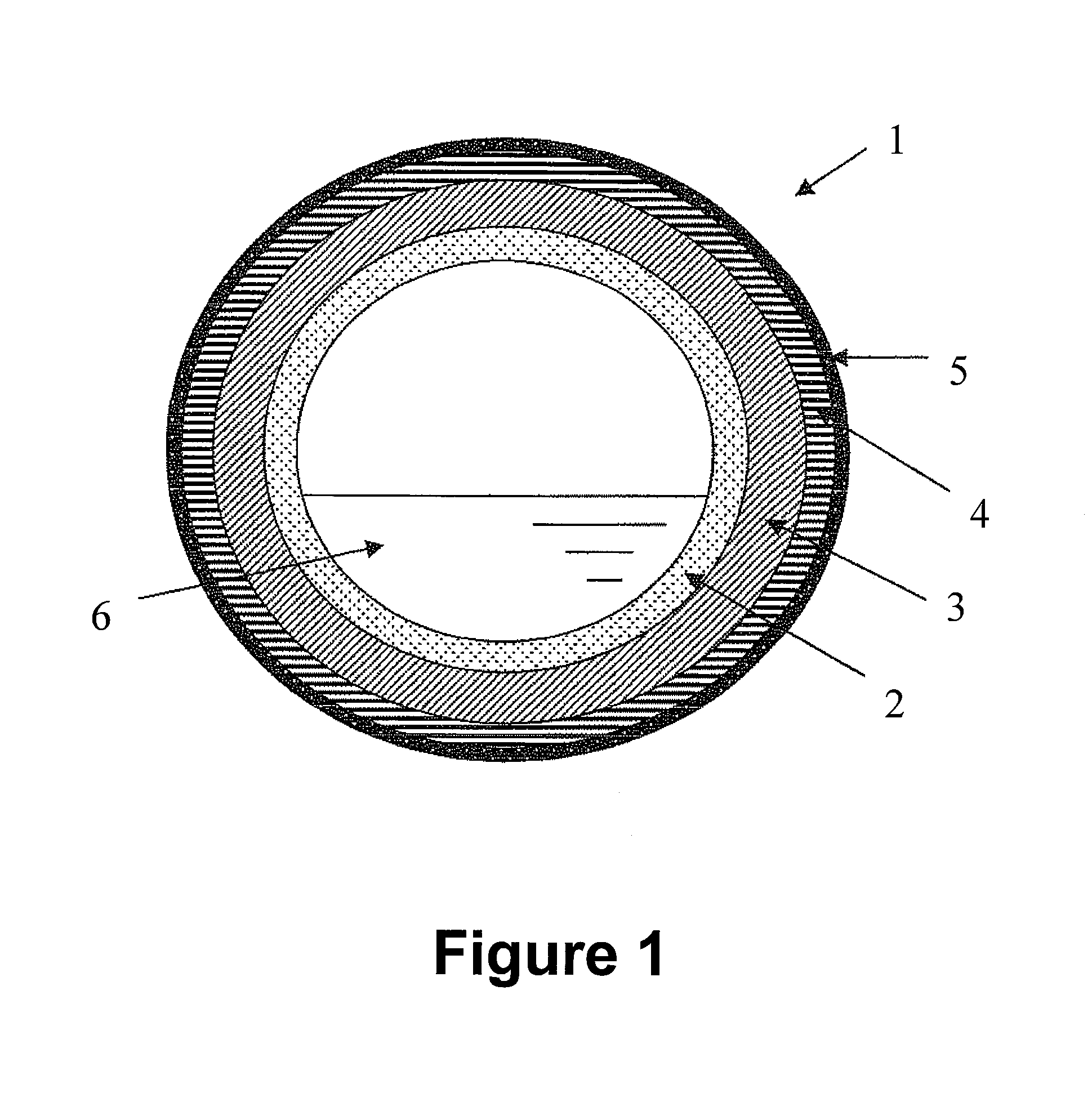
(1) Manufacture of a Melt Container

[0074]As members that constitute a melt container, refractory A (FLEXITE KERSIK-PB, made by NIHON TOKUSHU ROZAI Co., Ltd.) and refractory B (FLEXITE TM-65C3, made by NIHON TOKUSHU ROZAI Co., Ltd.) both having a composition and physical properties shown in Table 1, and a vertical cylindrical iron container (outer diameter: 75 cm, length: 75 cm, thickness: 6 mm) were used.

[0075]A lining of refractory A was made at a thickness of 50 mm inside the vertical cylindrical iron container to form a layer constituted of the refractory A (third layer). A lining of refractory B was further made at a thickness of 150 mm on the layer constituted of the refractory A (third layer) to form a layer constituted of the refractory B (second layer). Furthermore, a lining of refractory A was made at a thickness of 50 mm on the layer constituted of the refractory B (second layer) to form a layer constituted of the refractory A (first layer). Then, each of refractory A and ...


PUM

PropertyMeasurementUnit
porosityaaaaaaaaaa
thermal conductivityaaaaaaaaaa
porosityaaaaaaaaaa

Abstract

An object of the invention is to provide a container for holding a melt of a metal and/or a melt of a metal salt, in which a melt container allows keeping a small amount of heat radiation of the melt, suppressing penetration of the melt and development of breakage or cracking to the minimum, holding the melt suitably, and also preventing the melt from impurity contamination. The melt container of the invention is a container for holding the melt of the metal and/or the melt of the metal salt, and has, sequentially from inside of the container, a first layer constituted of a refractory having an apparent porosity of 12% or less, a second layer constituted of a refractory having a thermal conductivity (at 800° C.) of 4 W/m·K or less, and a third layer constituted of a refractory having a higher thermal conductivity than thermal conductivity of the second layer.

Description

TECHNICAL FIELD[0001]The present invention relates to a melt container.BACKGROUND ART[0002]As a container for holding a melt such as a molten metal or a molten salt (hereinafter, described also as “melt container”), a heat-resistant metal container, an iron container in the form of a ladle or the like, and so forth are used. The iron container in the form of the ladle or the like ordinarily has a ceramic lining inside the container. As a material for the lining, an unshaped refractory such as a castable refractory is generally used.[0003]In the iron container lined with such a refractory, if cracking or breakage is caused in a refractory layer while in use, the melt reaches an iron crust. Thus, the iron crust is damaged, and in a serious case, a problem of the melt leaching out occurs. In a case where the iron crust is damaged, peeling off the refractory layer and reconstruction of the unshaped refractory is needed. From an operational aspect, such a case decreases production effici...

Claims


Application Information

Patent Timeline
Patent Type & Authority Applications(United States)
IPC IPC(8): B65D1/40
CPCF27B14/00F27B14/08F27D1/0006B65D1/40C04B35/18C04B35/565C04B2235/9676C04B2235/3418C04B2235/3826C04B2235/77C04B2235/96C04B2235/9607C04B2235/3217
Inventor OHKUBO, SHUICHI
Owner JNC CORP
Why Eureka
Try Eureka