
Device and method for treating vascular abnormalities

a vascular abnormality and device technology, applied in the field of vascular devices, can solve the problems of weak vessel wall thinning, low survival chances, and eventually burst, and achieve the effect of accurate delivery and low profile of vascular devices

Active Publication Date: 2013-03-21
ST JUDE MEDICAL CARDILOGY DIV INC
View PDF11 Cites 65 Cited by
  • Summary
  • Abstract
  • Description
  • Claims
  • Application Information

AI Technical Summary

Benefits of technology

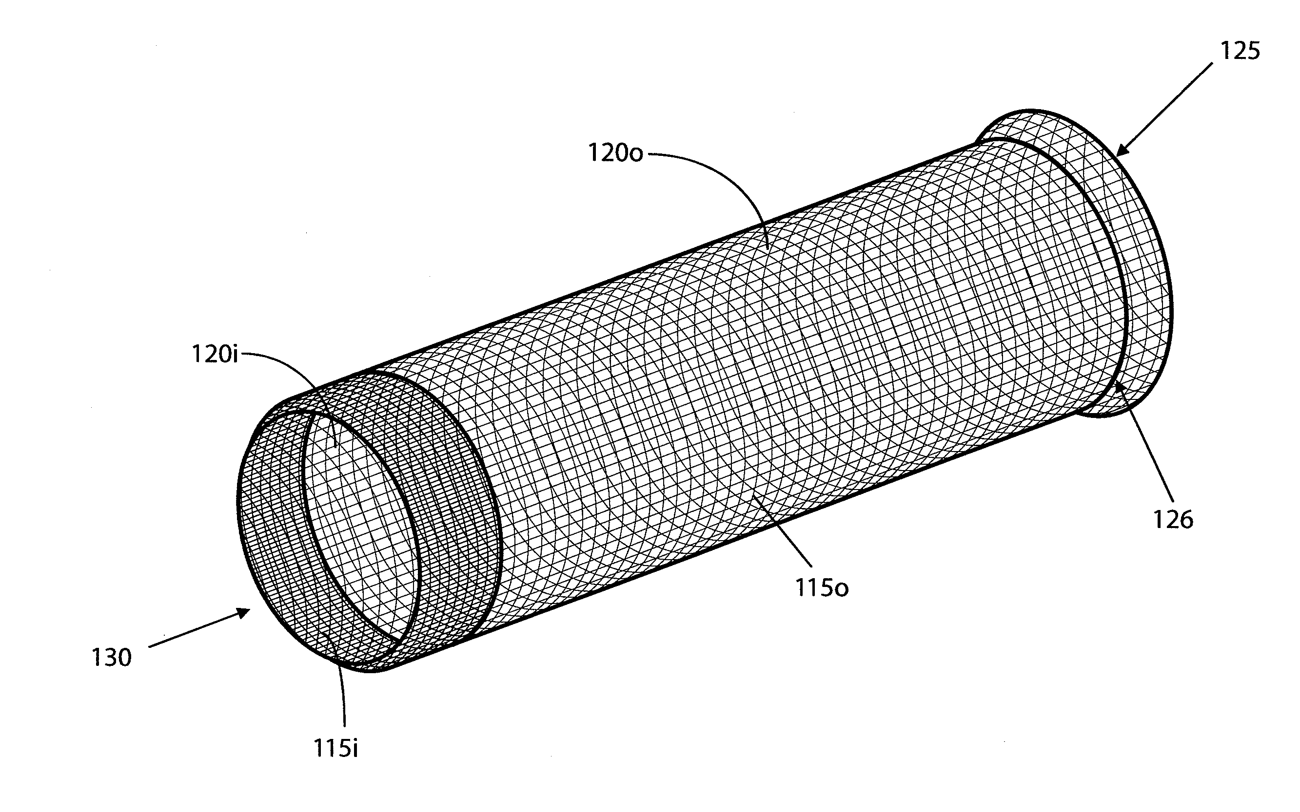
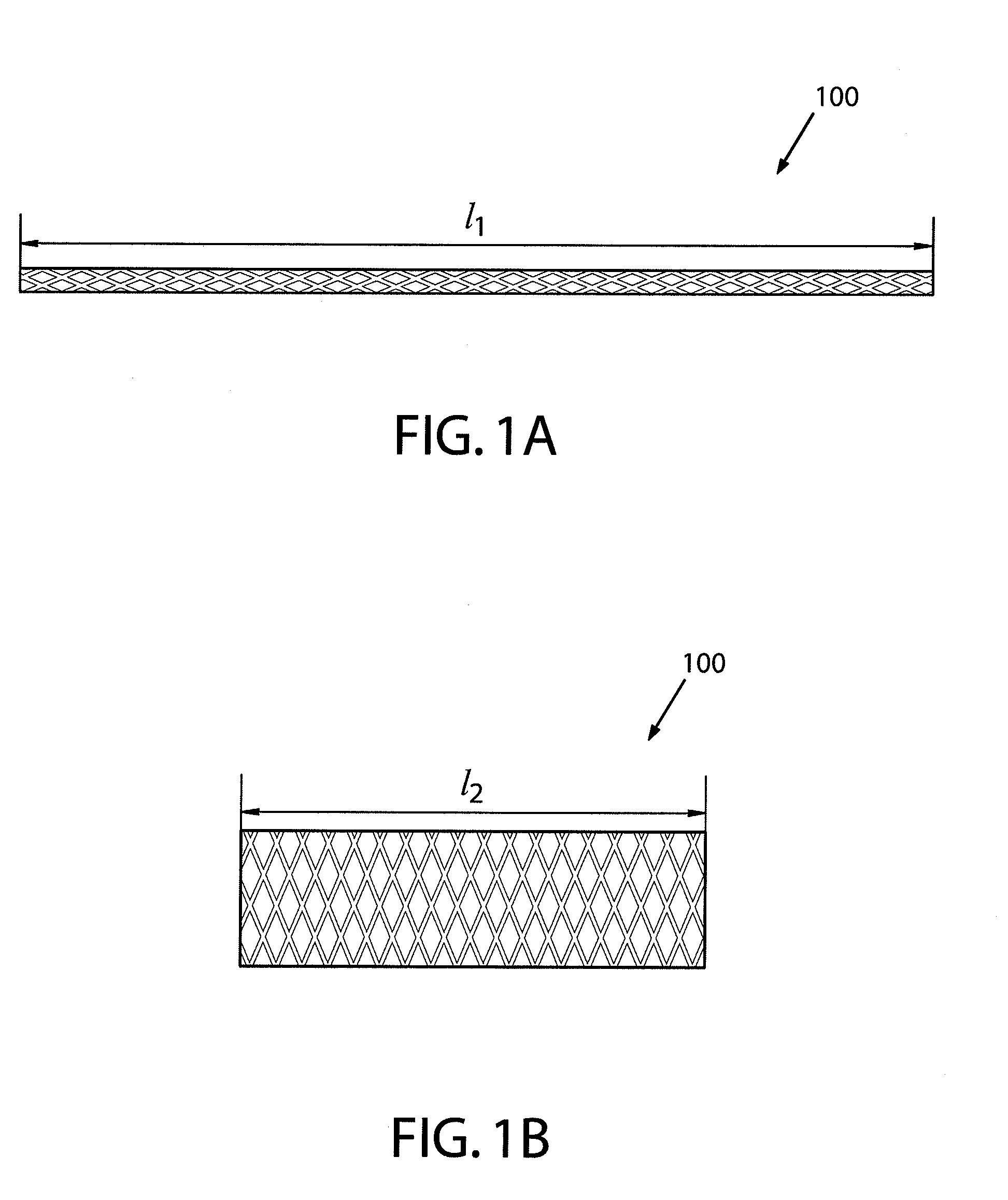
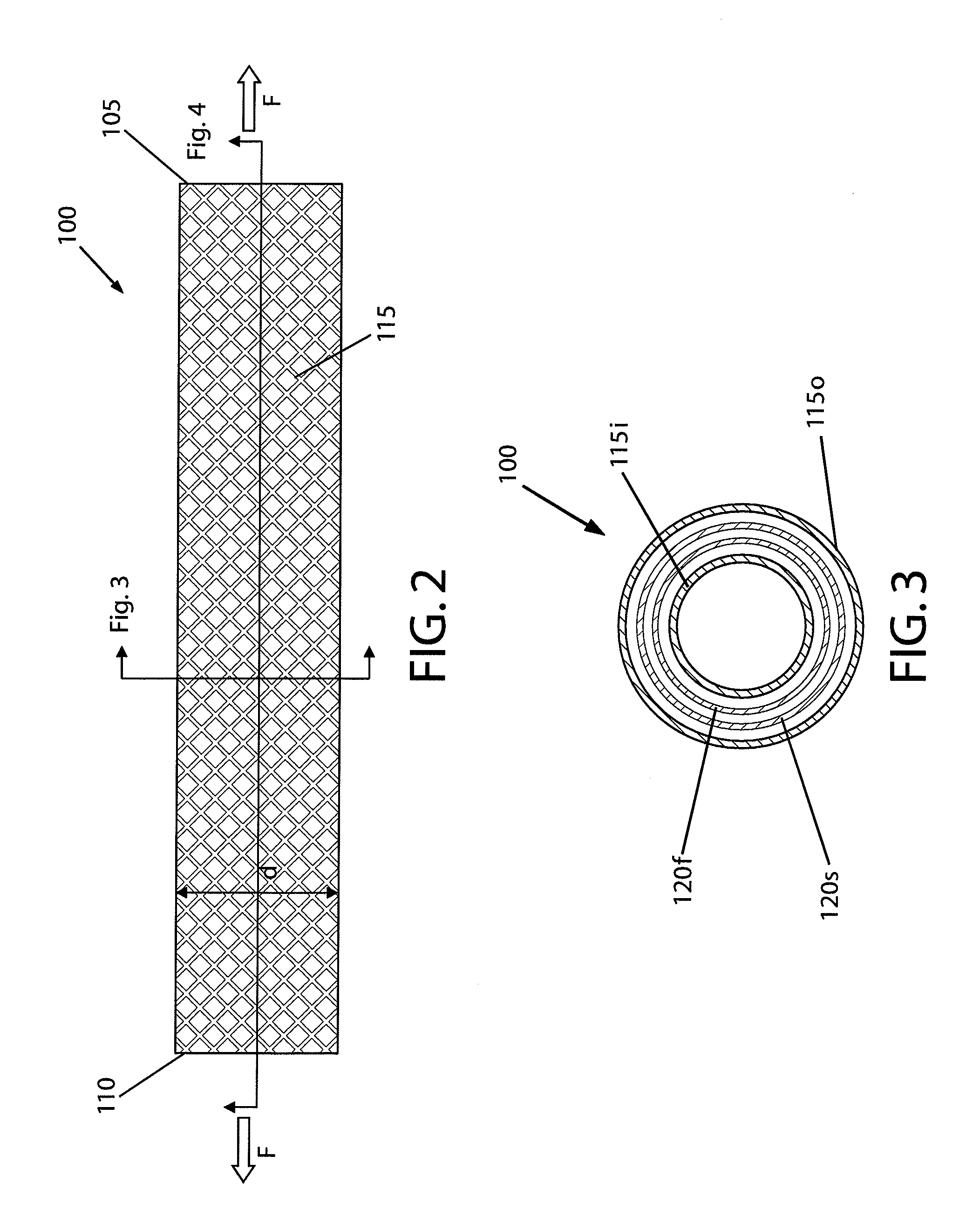
This patent describes a vascular device that can be contracted and expanded to be placed within a patient's body. The device has a tubular structure with two layers that move very little when the device is moved from its contracted state to its expanded state. The device also has a leading edge that helps guide it to the correct location and fixes it securely to the patient's body. The device is designed to have a low profile, especially at its distal end, to make it easy to insert and position within the patient's body.

Problems solved by technology

As blood flows through the aorta, the weak vessel wall thins over time and expands like a balloon, which can eventually burst if the vessel wall gets too thin.
Once an aortic aneurysm has ruptured, the chances of survival are low.
Surgical treatment is complex, however, and may pose additional risks to the patient, especially the elderly.
Another consideration is the occurrence of endoleaks as a result of blood flowing around the stent, which may cause further weakening of the vessel wall at the site of the aneurysm.
Furthermore, the size of the delivery catheter may affect the ability of the surgeon to manipulate the catheter within the patient's vasculature.
For example, when the aneurysm is located in a vessel having a small diameter and / or when the vessel diameter is reduced in size due to arteriosclerosis, larger delivery catheters may not be used or, at best, may result in trauma to the vascular tissue.

Method used


Image

  • Device and method for treating vascular abnormalities
  • Device and method for treating vascular abnormalities
  • Device and method for treating vascular abnormalities

Examples


Embodiment Construction

[0039]Embodiments of the present invention now will be described more fully hereinafter with reference to the accompanying drawings, in which some, but not all embodiments of the invention are shown. Indeed, the invention may be embodied in many different forms and should not be construed as limited to the embodiments set forth herein; rather, these embodiments are provided so that this disclosure will satisfy applicable legal requirements. Like numbers refer to like elements throughout.

[0040]As described in greater detail below, one embodiment of a vascular device generally includes a tubular structure comprising an inner layer and an outer layer, as well as an occluding structure disposed between the inner and outer layers. The vascular device may be configured to move between a contracted state when constrained within a delivery device and an expanded state when deployed from the delivery device for delivery to a target site within the vessel lumen. In some cases, the inner and o...


PUM


Abstract

A vascular device is provided that includes a tubular structure and an occluding structure. The tubular structure has inner and outer layers, with the occluding structure located between the inner and outer layers. Each of the inner and outer layers may define a different pick count, and the tubular structure may include a leading edge at a transition between the pick counts. The leading edge may be disposed at the distal end of the vascular device when the device is deployed from a delivery device. Furthermore, the occluding structure may have first and second layers formed by the inversion or eversion of the occluding structure and the subsequent coupling of its free ends to form a continuous structure. Thus, any loose ends may be sealed to minimize unraveling and / or shifting of the occluding structure within the tubular structure. A method of making the vascular device is also provided.

Description

BACKGROUND[0001]I. Field of the Invention[0002]Embodiments of the present invention relate generally to vascular devices for treating certain vascular abnormalities, such as aneurysms. In particular, embodiments are directed to vascular devices including stents, grafts, and stent-grafts and methods for making vascular devices having a low profile for delivery and deployment in a patient's vasculature, such as the vessels of the thoracic area.[0003]II. Description of the Related Art[0004]Stents and grafts, both biological and synthetic, have been used for a large array of reparative vascular procedures, such as to treat obstructive vessels and aneurysms. An aortic aneurysm, for example, is a weakened, enlarged area in the aorta, which is the main blood vessel that carries blood from the heart to the rest of the body. Weaknesses in the aortic wall may be caused by medical conditions, such as arteriosclerosis. As blood flows through the aorta, the weak vessel wall thins over time and e...

Claims


Application Information

Patent Timeline
IPC IPC(8): A61F2/90B21F45/06A61M29/00
CPCA61F2/07A61F2/852A61F2/90A61F2250/0017A61F2250/0048A61B17/12109B21F45/008A61F2210/0076A61F2220/0075A61F2230/0067A61F2250/0063
Inventor RUSSO, PATRICKOSLUND, JOHNHEIDNER, MATTHEW C.AKERS, JESSICA
Owner ST JUDE MEDICAL CARDILOGY DIV INC
Learn More