
Electrical construction machine

a construction machine and electric technology, applied in the direction of soil shifting machines/dredgers, transportation and packaging, propulsion parts, etc., can solve the problems of reducing the life of the battery at an early time, unable to cool the oil tank and the like which are arranged on the downstream side of the air flow, and unable to achieve the effect of efficiently cooling, efficiently cooling, and efficient cooling

Inactive Publication Date: 2013-03-21
NIHON KENKI CO LTD
View PDF5 Cites 27 Cited by
  • Summary
  • Abstract
  • Description
  • Claims
  • Application Information

AI Technical Summary

Benefits of technology

The present invention provides an electrical construction machine that can protect the battery from heat generated by installed equipment and efficiently cool the equipment in the machine room. This is achieved by using a radiator to cool the electric motor and inverter, and an oil cooler to cool the oil tank. These features improve the machine's performance and reduce the risk of damage to the battery and equipment.

Problems solved by technology

For this reason, with the electrical hydraulic excavator according to the conventional art, there is a problem in that heat which is generated from the hydraulic pump, the electric motor, the oil tank, the heat exchanger, and the like is easily transmitted to the battery accommodated in the same accommodating space as these items of equipment, disadvantageously causing the life of the battery to decline.
Accordingly, as this heated cooling air is supplied toward the battery, there is a problem in that the life of the battery is reduced at an early time.
Meanwhile, in a case where the air in the accommodating space is exhausted to the outside by the cooling fan, since the air in the accommodating space is sequentially supplied to the battery, the heat exchanger, the electric motor, the hydraulic pump, and the oil tank, there is a problem in that it becomes impossible to sufficiently cool the oil tank and the like which are arranged on the downstream side of the air flow.

Method used


Image

  • Electrical construction machine
  • Electrical construction machine
  • Electrical construction machine

Examples


Embodiment Construction

[0047]Hereafter, a construction machine according to an embodiment of the present invention will be explained in greater detail with reference to the accompanying drawings, by citing a hydraulic excavator as an example.

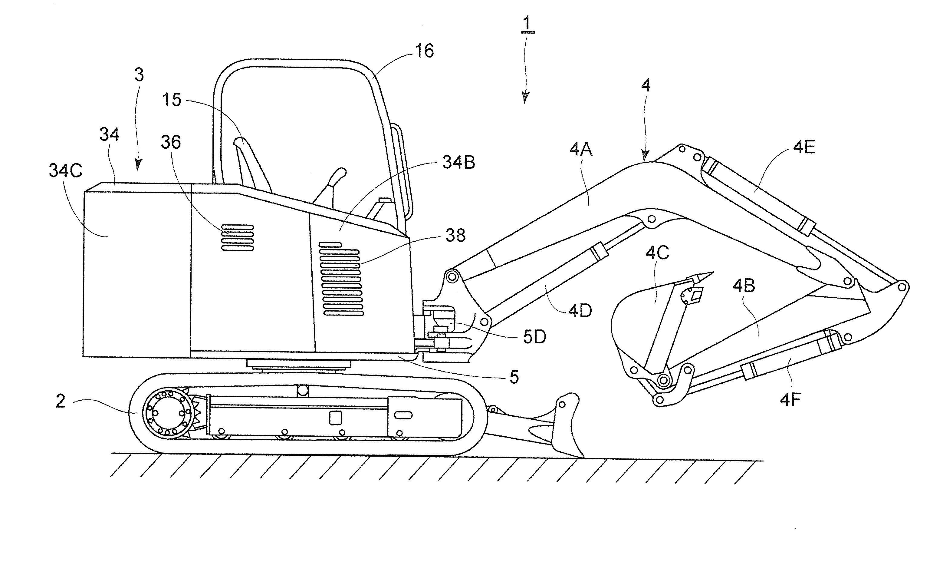
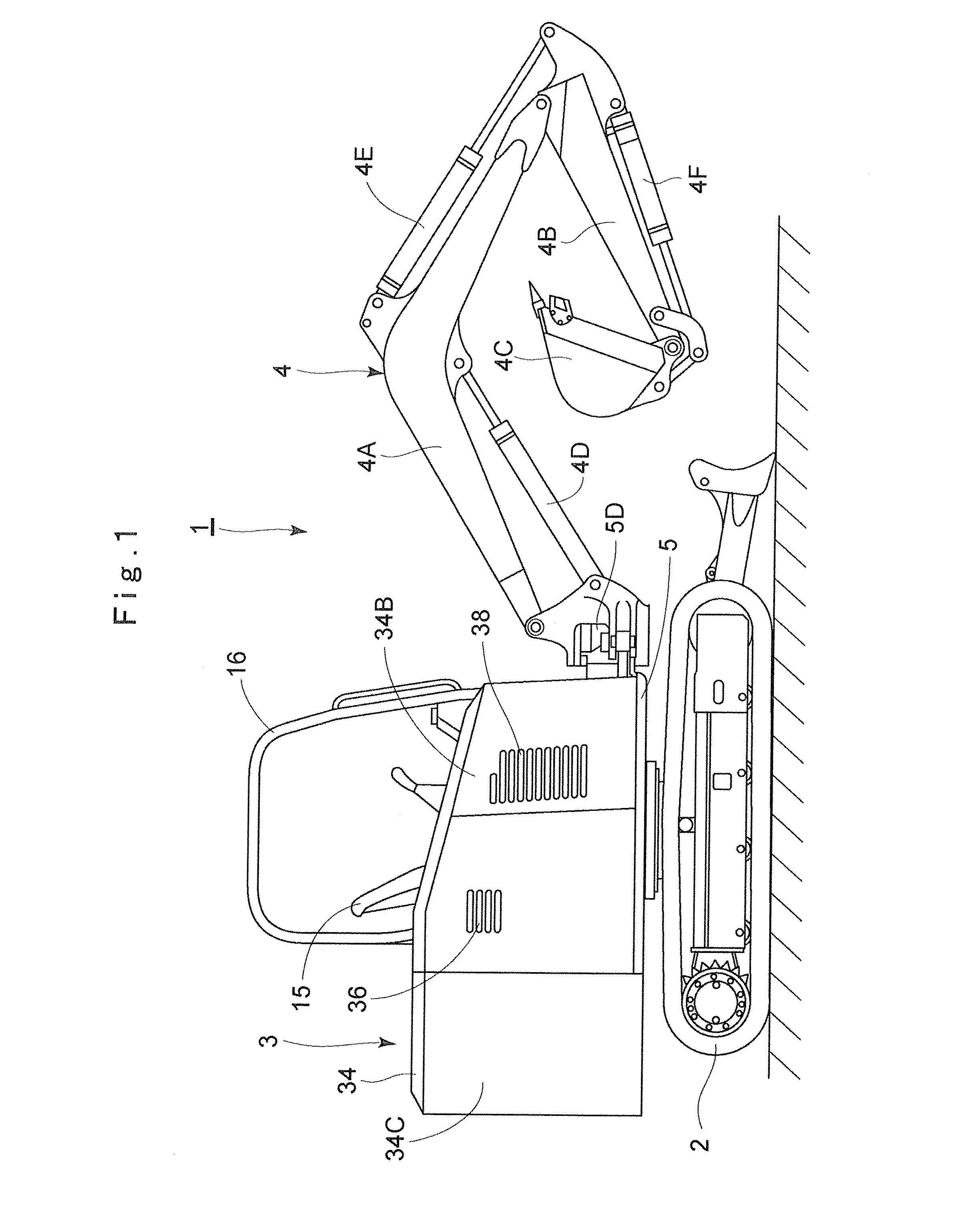
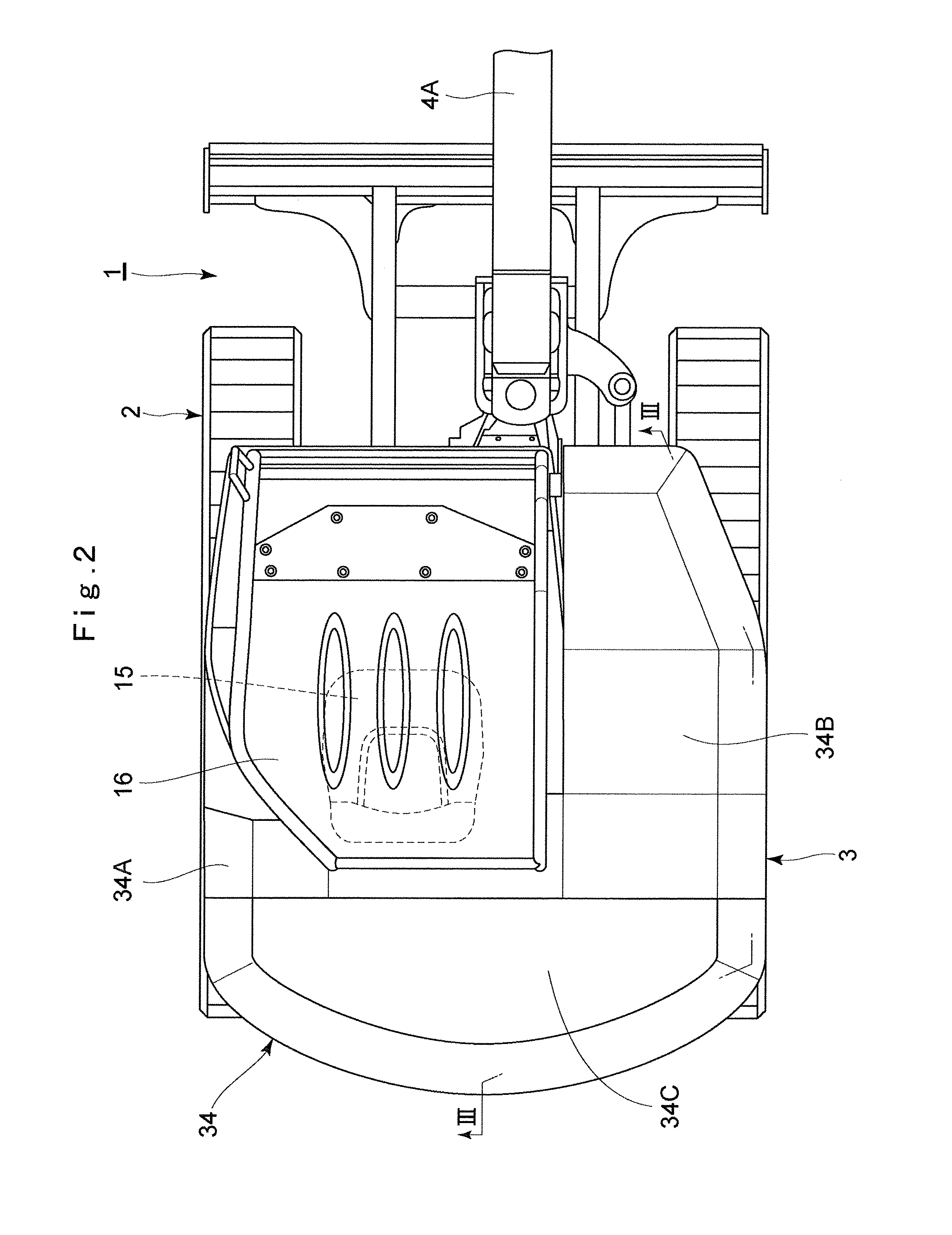
[0048]In the drawings, designated at 1 is an electrical hydraulic excavator, and this hydraulic excavator 1 is constituted by a crawler type automotive lower traveling structure 2 and an upper revolving structure 3 which is swingably mounted on the lower traveling structure 2 and constitutes a vehicle body together with the lower traveling structure 2. A swing type working mechanism 4 for performing such as the operation of excavating earth and sand is provided on a front side of the upper revolving structure 3. The working mechanism 4 is constituted by a boom 4A, an arm 4B, a bucket 4C, a boom cylinder 4D, an arm cylinder 4E, a bucket cylinder 4F, and the like.

[0049]The hydraulic excavator 1 has a hydraulic pump 17, an electric motor 18, and the like which will be de...


PUM


Abstract

A hydraulic pump, electric motor, inverter, oil tank, heat exchanger, and battery are mounted on a revolving frame, and are covered by an exterior cover. The revolving frame is provided with a partition plate, and the interior of the exterior cover is partitioned by the partition plate into a machine room for accommodating the hydraulic pump and the electric motor and into a battery room for accommodating the battery. A cooling fan is arranged in the machine room so that outside air is introduced into the machine room through an oil tank cooling air inlet port and an inverter cooling air inlet port which are provided in the exterior cover. This outside air cools the hydraulic pump, the electric motor, and the oil tank in the machine room and is exhausted to the outside of the machine room through an exhaust port.

Description

TECHNICAL FIELD[0001]The present invention relates to an electrical construction machine such as a hydraulic excavator, a wheel loader, or the like equipped with an electric motor as its power source.BACKGROUND ART[0002]Generally, a construction machine such as a hydraulic excavator which is used in excavating operations and demolition operations employs an engine (internal combustion engine) as a power source, and a hydraulic pump is driven by this engine. The arrangement provided is such that pressure oil (working oil) is supplied from the hydraulic pump to various hydraulic actuators including a hydraulic motor for traveling, a hydraulic motor for revolving, a hydraulic cylinder for constituting a working mechanism, and the like.[0003]Meanwhile, in order to prevent the working environment from deteriorating due to exhaust gas from the engine at the time of performing an excavating operation or a demolition operation within, for example, a building structure such as a storage, a b...

Claims


Application Information

Patent Timeline
IPC IPC(8): E02F9/22
CPCB60K11/08B60Y2200/412E02F9/0866E02F9/22E02F9/0891E02F9/207E02F9/226E02F9/0883E02F9/0808
Inventor YUNOUE, MASAYUKINOGUCHI, AKIRA
Owner NIHON KENKI CO LTD
Learn More