
Rear bogie-type suspension

a bogie-type suspension and bogie-type technology, applied in the direction of suspensions, suspensions, transportation and packaging, etc., can solve the problems of affecting the construction of the anchor frame with the chassis, affecting the safety of drivers, so as to reduce the consumption of materials and labor, improve the assembly, and reduce the weight

Inactive Publication Date: 2013-03-21
SUSPENSYS SISTEMAS AUTOMOTIVOS
View PDF18 Cites 23 Cited by
  • Summary
  • Abstract
  • Description
  • Claims
  • Application Information

AI Technical Summary

Benefits of technology

The patent describes a new rear bogie-type suspension system for trucks that improves assembly, reduces weight, materials and labor consumption. It also includes a spring pack with a pivoting bearing for better load distribution, an axle rebound stop to prevent axle detachment in case of extreme strain, and an elastomeric cushion to improve vehicle comfort.

Problems solved by technology

Although these suspensions are more expensive, compared to spring pack and equalizer models, they are the most used for severe applications in trucks in off-road conditions, due to the need to reduce the time and maintenance frequency, having more vehicle availability to work.
These suspensions are also used for trucks on road applications, due to legal requirements in relation to combinations with trailers and / or semi-trailers, being the suspensions used in these cases very rigid, therefore low comfort for drivers due to vibration.
The pivot located in the lower part of the spring pack is normally positioned in a region far from and right below the chassis, owing to the space and conditions available by the structural disposition of the vehicle, thus hampering the construction of the anchor frame with the chassis, which supports the articulating bearing of the suspension spring.
In the suspension described above, the concept of bearing is idealized in a complex manner, and to be manufactured requires the use of complex and more expensive technologies and processes.
The document cited above also shows a system for fastening the bearing to the chassis by way of fasteners or screws, having the disadvantage of hampering the vehicle assembly process, by requiring an approximation and accurate alignment to coincide with the housing holes in the support.
It must be highlighted that to mount said bearing on the chassis support, it is necessary to use special means and tools, suitable for moving the bearing until it coincides with the housing holes in the support, further worsened by the residual distortion resulting from the elastic memory characteristic which normally results from the manufacturing process thereof, requiring an additional effort from the assembler to correct it, making the assembly process hard and more expensive.
One of the drawbacks of the axles rebound stop cited in the current art is the high cost, because they are made of various and complex components, also due to the various manufacturing processes they undergo, and the installation difficulty, which generates wasted material and labor and, the necessity for more logistic controls.
Another drawback presented in said axles and suspension rebound stop is that since they are comprised of various and complex components, they tend towards failure due to the variability of the manufacturing and installation processes, thus being subject to functional problems, which may cause damage to the suspension, to the vehicle, and offer risk of accidents with other vehicles on the road, and to their users.
The drawback of the system described is that it is comprised by various and complex components and, which consequently increase costs and also propensity to failures.
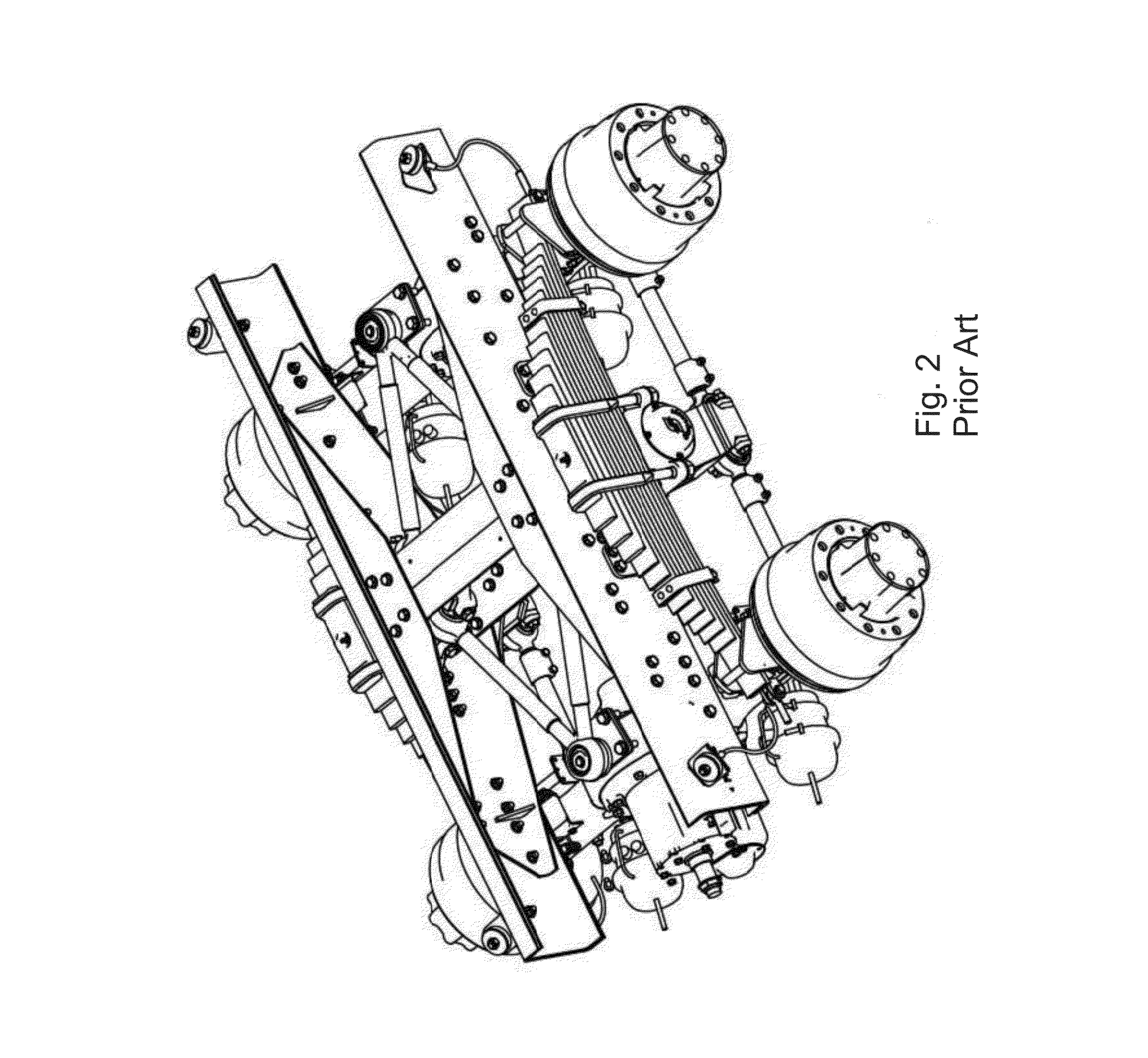
Among the drawbacks found in the rear bogie-type suspensions for the state of the art trucks, the most relevant is the constructive difficulty of the anchoring of the pivoting bearing, owing to the fact that it is positioned beneath the spring pack and far from the chassis, which requires a construction of a more complex frame, with greater consumption of material and more manufacturing processes, resulting in considerably higher weight and costs.
Another drawback presented in the rear bogie-type suspensions used today in trucks is the difficulty in assembling the kit of springs and bearing on the support and the chassis, causing wastage and lost time with more stages in the assembly line and the necessity for specific devices.

Method used


Image

  • Rear bogie-type suspension
  • Rear bogie-type suspension
  • Rear bogie-type suspension

Examples


Embodiment Construction

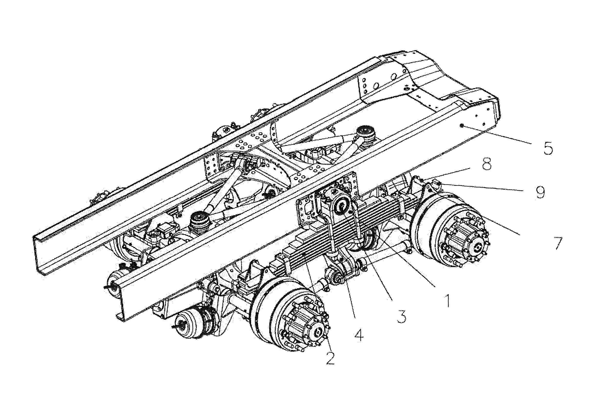
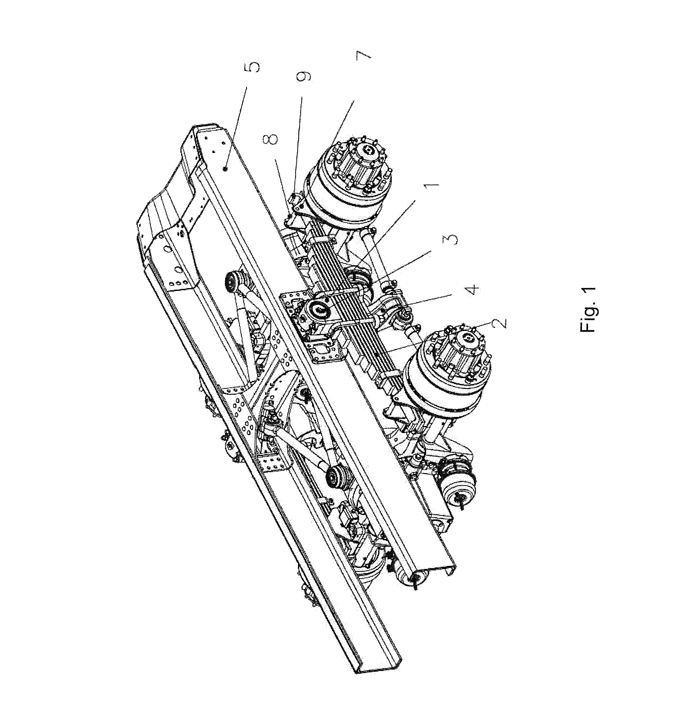
[0035]In accordance with the illustrated in the accompanying drawings, the present rear bogie-type suspension used preferably in trucks, comprised of spring pack, upper and lower reaction rods for the longitudinal linkage of the axles, supports for housing the reaction rods on the axles and on the chassis, springs brackets housed in the axles and, other suspension components, comprises a pivoting bearing (1) disposed and fastened on upper part of the spring pack (2) and to an anchor pin (3), fixed and housed in a central hanger (4), and both bolted laterally to the chassis (5), there being also provided a axle rebound stop (6) in combination with leaf spring ends, bolted to the vehicle axles, which comprises a spring bracket (7), comprised of a base and two substantially triangular side plates (19), which are interconnected by the upper part by way of a stop pin (8), which acts as a limiter for at least one leaf spring which is provided with a hook (9) at the end.

[0036]The pivoting ...


PUM


Abstract

The present patent of invention refers to a rear bogie-type suspension used preferably in trucks, having a pivoting bearing (1) disposed on upper part of the spring pack (2), positioned between the two axles and laterally on each side of the chassis (5), said pivoting bearing (1) comprised of an anchor pin (3) fastened to a hanger (4) and to the chassis (5), in a robust manner to withstand the extreme strains to which this kind of suspension is normally submitted, also favoring assembly conditions, weight reduction, reduced consumption of materials and labor, also having an axle rebound stop (6) in combination with spring pack (2) in order to provide greater safety and durability to its components.

Description

[0001]The present patent of invention refers to a new rear bogie-type suspension used preferably in trucks, having a pivoting bearing on upper part of the spring pack, positioned between the two axles and laterally on each side of the chassis, said pivoting bearing comprised of an anchor pin fastened to a hanger and to the chassis in a robust manner to withstand the extreme strains to which this kind of suspension is normally submitted, also to improve the assembly conditions, weight reduction, reduced consumption of materials and labor.[0002]In the rear bogie-type suspension of the present invention there is also provided a new set of axle rebound stop in combination with spring pack which avoids the release of the axle, in the event that the suspension undergoes on an extreme strain, and if any primary link component of the axle fails, providing greater safety and durability of its components.[0003]Said axle rebound stop comprises a spring pack having hooks at the ends, where the ...

Claims


Application Information

Patent Timeline
Patent Type & Authority Applications(United States)
IPC IPC(8): B60G11/02B60G9/02
CPCB60G5/03B60G9/00B60G2204/121B60G11/107B60G11/12B60G11/04
Inventor PIZZETA, REMI
Owner SUSPENSYS SISTEMAS AUTOMOTIVOS
Learn More