
Engine exhaust purification device

a technology for purifying devices and engines, applied in machines/engines, process and machine control, instruments, etc., can solve problems such as ammonia slip promotion, and achieve the effect of enhancing nox purification and accurate estimation of ammonia adsorption amoun

Active Publication Date: 2013-03-14
NISSAN DIESEL MOTOR CO +2
View PDF2 Cites 30 Cited by
  • Summary
  • Abstract
  • Description
  • Claims
  • Application Information

AI Technical Summary

Benefits of technology

The present invention relates to a control device for reducing emissions in combustion engines. The device incorporates a catalytic reaction model which accurately estimates the amount of ammonia adsorbed onto the catalyst without the need for maps. This model is used to accurately calculate the amount of ammonia needed for NOx purification, and to adjust the amount of ammonia supplied to the catalyst accordingly. The device also includes a second catalytic reaction model that predicts the oxidation reaction of nitrogen monoxide in the oxidation catalyst, which affects the amount of ammonia needed for NOx purification. This model is used to estimate the NO2 ratio in the exhaust gas flowing into the NOx catalyst and to adjust the amount of ammonia supplied accordingly. The invention aims to optimize ammonia utilization for NOx purification while also suppressing ammonia slip.

Problems solved by technology

On the other hand, when the urea aqueous solution continues to be supplied at an increasing load operation such as acceleration without taking the amount of the adsorbed ammonia into consideration, the desorption of the adsorbed ammonia occurs owing to the rise of an exhaust temperature, which results in the promotion of the ammonia slip.

Method used


Image

  • Engine exhaust purification device
  • Engine exhaust purification device
  • Engine exhaust purification device

Examples


Embodiment Construction

[0039]Hereinafter, embodiments of the present invention will be described with reference to the drawings.

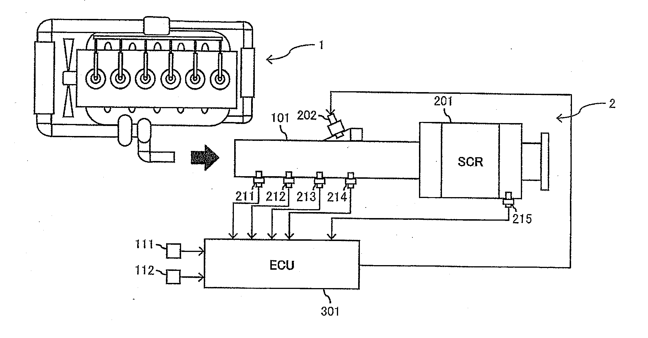
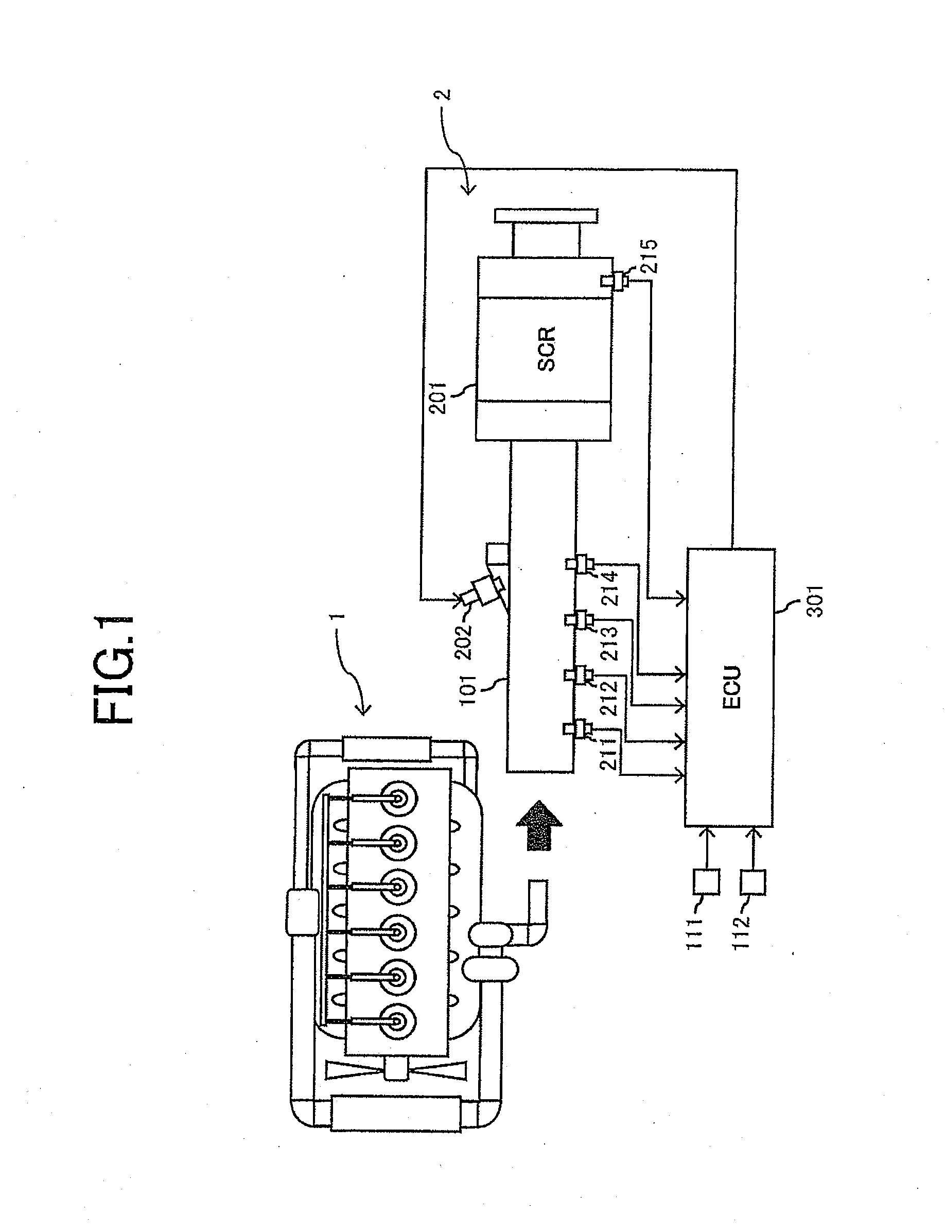
[0040]FIG. 1 is a constitutional view of a diesel engine (hereinafter referred to simply as “the engine”) 1 and an exhaust purification device 2 according to a first embodiment of the present invention.

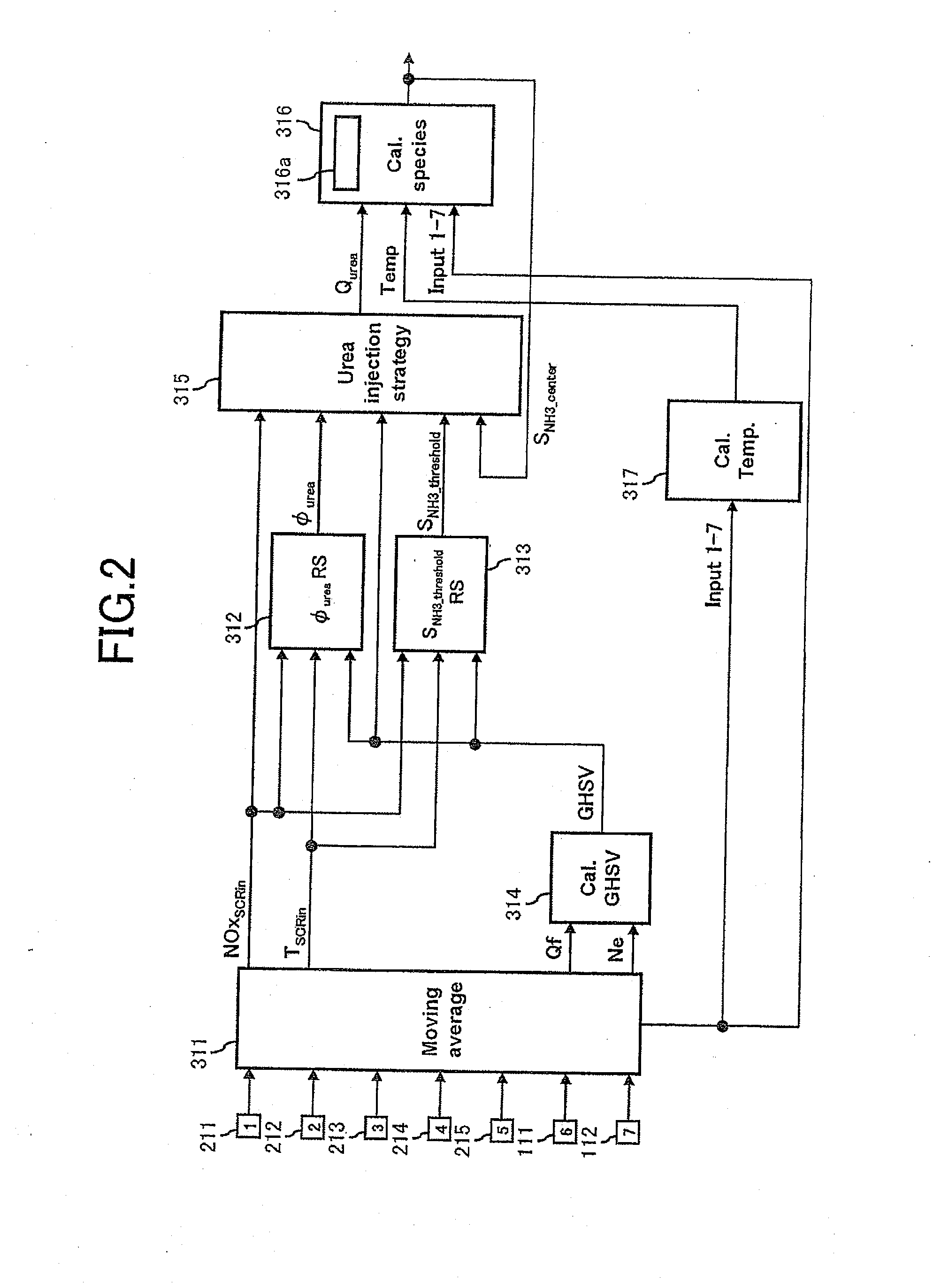
[0041]The exhaust purification device 2 according to the present embodiment includes a selective reduction type NOx catalyst 201 disposed around an exhaust pipe 101 of the engine 1, and an urea aqueous solution injector 202 (corresponding to “the reducing agent adding device”) disposed so that an urea aqueous solution can be supplied to an exhaust gas on an upstream side of the NOx catalyst 201, and NOx discharged from the engine 1 is reduced by using, as a reducing agent, ammonia from a generation source of the urea aqueous solution supplied to the exhaust gas by the urea aqueous solution injector 202. Although not shown, in the present embodiment, an oxidation catalyst is dispose...


PUM


Abstract

An engine exhaust purification device comprises: a selective reduction type NOx catalyst; an oxidation catalyst disposed on an upstream side of the NOx catalyst; a reducing agent adding device which adds an NOx reducing agent to an exhaust gas of an engine; a control device which controls the reducing agent adding device; and an NO2 ratio calculation device which estimates an NO2 ratio of the exhaust gas flowing into the NOx catalyst. The NO2 ratio of the exhaust gas flowing into the NOx catalyst is calculated by a catalytic reaction model where the oxidation reaction of NO in the oxidation catalyst is numerically formulated, and the NO2 ratio is reflected to calculate an amount of ammonia adsorbed on the NOx catalyst by a catalytic reaction model where a chemical reaction concerned with the reduction of NOx in the NOx catalyst is numerically formulated.

Description

[0001]This application is a Continuation of PCT Application PCT / JP2011 / 056559, filed Mar. 18, 2011, which claims priority from prior Japanese Patent Application No. 2010-069326, filed Mar. 25, 2010, the entire contents of all of which are incorporated herein by reference.TECHNICAL FIELD[0002]The present invention relates to an engine exhaust purification device which reduces nitrogen oxides (hereinafter abbreviated to “NOx”) in an exhaust gas by use of ammonia as a reducing agent to purify the exhaust gas, and more particularly, it relates to a technology of estimating an amount of ammonia adsorbed on a catalyst layer of an NOx catalyst by a numerical model to control an amount of the ammonia to be supplied to the NOx catalyst in accordance with the calculated amount of the adsorbed ammonia.BACKGROUND ART[0003]In a catalyst system which reduces NOx discharged from a typical lean burn engine of a diesel engine by use of ammonia as a reducing agent to purify the exhaust gas, the use o...

Claims


Application Information

Patent Timeline
IPC IPC(8): G05B17/00F01N3/18
CPCF01N3/208F01N2560/025F01N2560/026F01N2560/06F01N2610/02F01N2610/146Y02T10/24F01N2900/0411F01N2900/1402F01N2900/1622F01N3/18G05B17/00F01N2900/0406F01N3/106Y02T10/12
Inventor MASAKI, NOBUHIKOHIRATA, KIMINOBUKUSAKA, JINKATO, HIDEAKINOTAKE, YASUMASA
Owner NISSAN DIESEL MOTOR CO
Learn More