
Fibrous insert consisting of a single layer and equipped with a contactless communication electronic device

a technology of electronic devices and inserts, applied in instruments, other printing materials, and antennas, etc., can solve the problems of cavity bottom, difficult forgery by forgers, and inability to receive chips, etc., and achieve the effect of not increasing the thickness of the inser

Inactive Publication Date: 2013-03-14
ARJO WIGGINS SECURITY SAS
View PDF31 Cites 33 Cited by
  • Summary
  • Abstract
  • Description
  • Claims
  • Application Information

AI Technical Summary

Benefits of technology

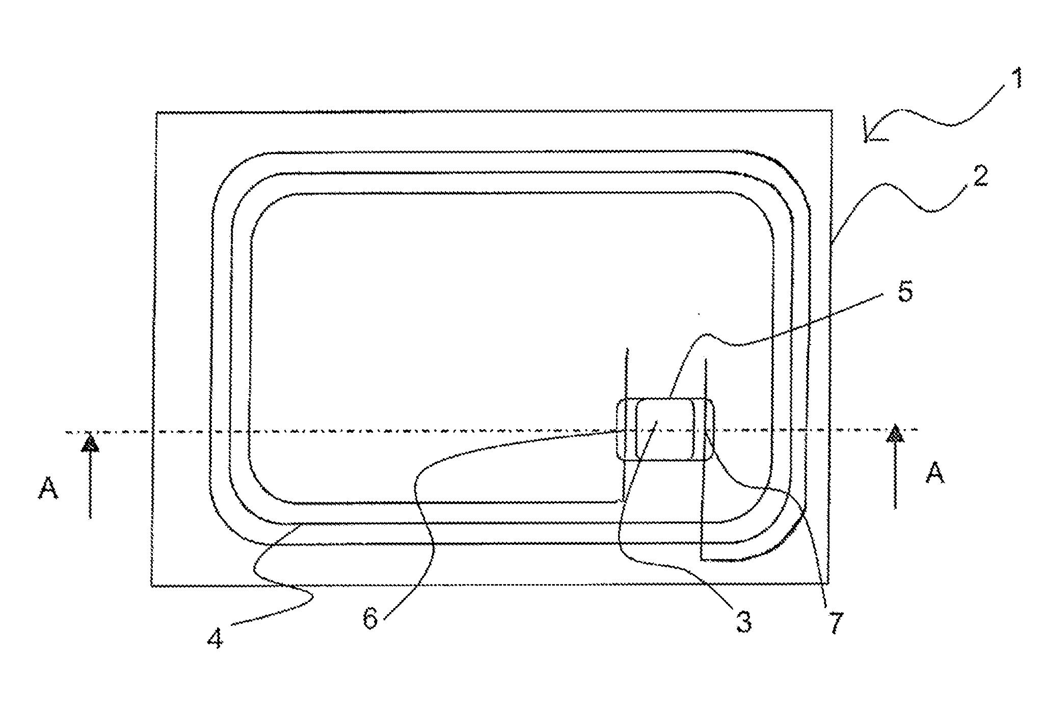
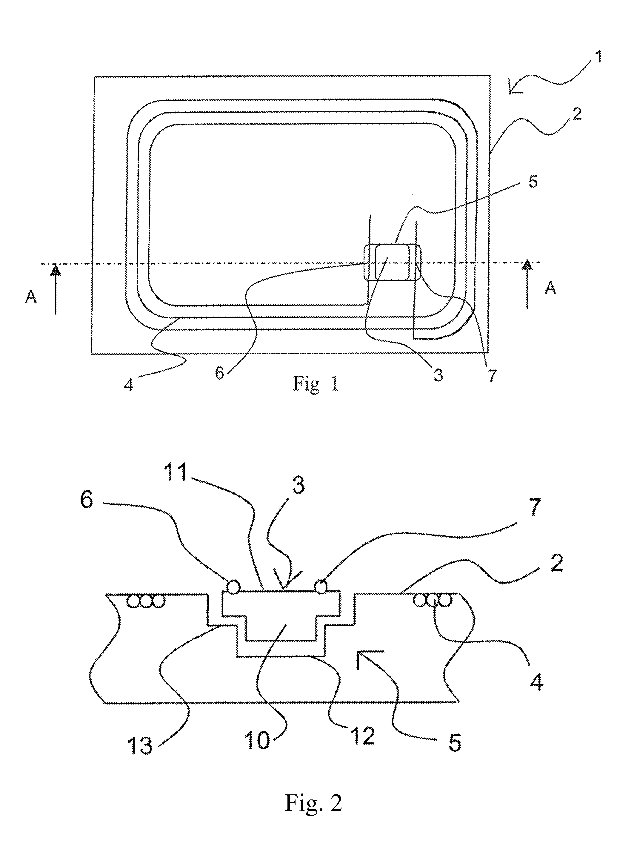
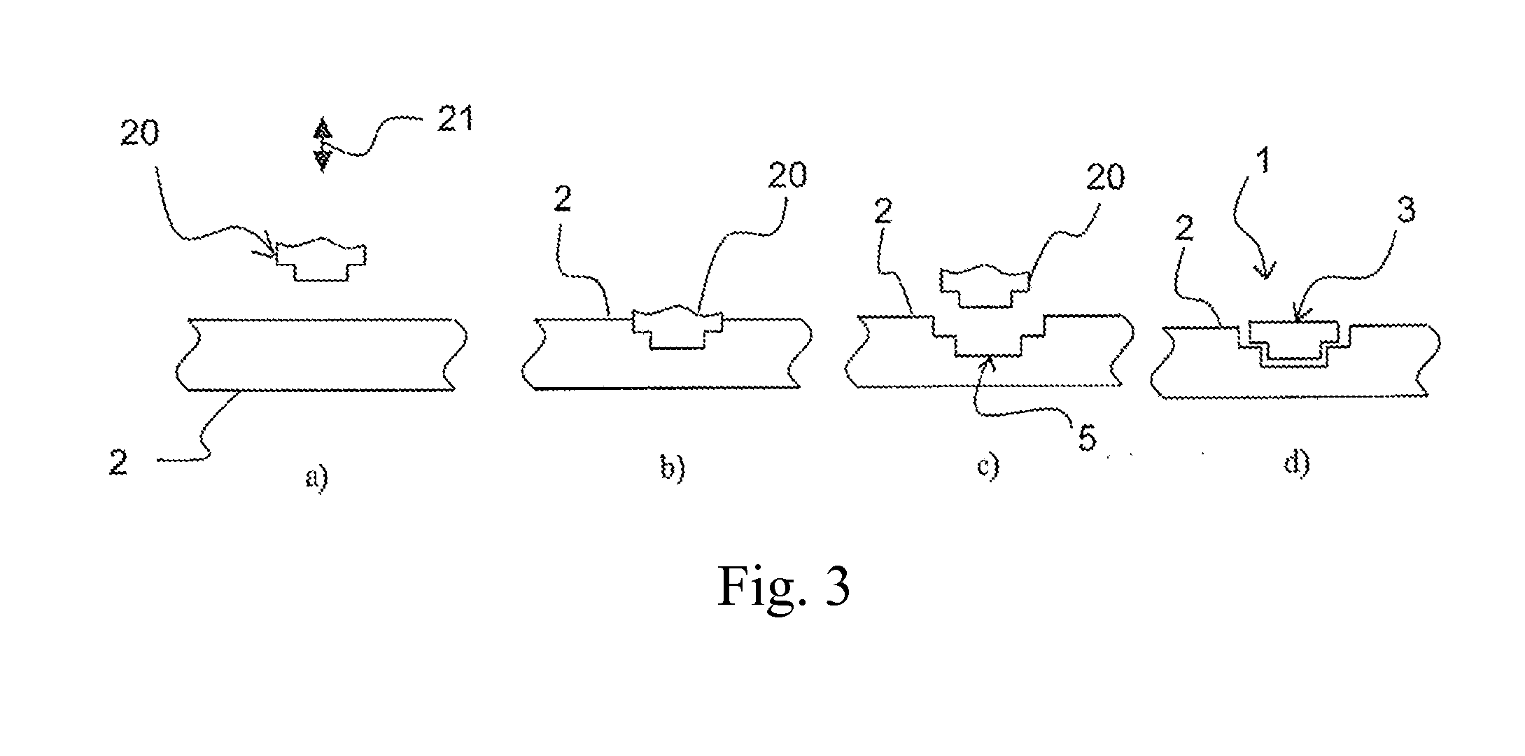
The invention proposes an insert with a contactless communication electronic device that is protected from external attacks and stresses. The insert has a cavity that opens out onto a single face of a fibrous support, which means the other face is protected by the support. This arrangement makes it secure to hold the electronic device in place without the need for additional measures. The fabrication method used is simple and inexpensive. The technical effect of the invention is to provide an improved security measure for documents.

Problems solved by technology

Such inserts therefore constitute a security means which is difficult to forge by a forger.
The rotation of the tool results in a cavity bottom which is usually not flat and therefore not suitable for receiving a chip which is substantially flat.
Furthermore, such a method implemented on a fibrous support causes a ripping out of the fibres and a deformation of the cavity.
An insert provided with such a cavity does not provide optimum protection of the chip which is accessible and can therefore be subjected to stresses and / or attacks, notably mechanical or chemical.
The formation of a cavity by means of a laser is relatively lengthy and costly and does not make it possible to achieve sufficient depths to house the chip in the support of the insert without increasing the thickness.
Furthermore, the laser burns, damages and blackens the material of the support which causes the material of the support to be embrittled at the level of the cavity.
The method for obtaining this insert is relatively long and costly since it involves a large number of steps.
On the one hand, the thermoplastic material is certain to melt under the action of heat which can be very problematical given that the mechanical method used to form the cavity involves raising the temperature in the cavity formation area.
Such a material therefore has a tendency to creep randomly during the cavity forming operation.
The result of this is that the cavity exhibits deformations and is therefore not suitable for housing the electronic device.
Also, with such an insert, the electronic device is not protected from external attacks and stresses, notably mechanical and chemical, since it is accessible and visible on both faces of the insert.

Method used


Image

  • Fibrous insert consisting of a single layer and equipped with a contactless communication electronic device
  • Fibrous insert consisting of a single layer and equipped with a contactless communication electronic device
  • Fibrous insert consisting of a single layer and equipped with a contactless communication electronic device

Examples


example 1

[0082]The fibrous support is fabricated on the paper machine so that the support comprises a fibrous base consisting of approximately 15% dry weight relative to the finished paper of polyamide synthetic fibres, approximately 6 mm long and approximately 1.7 dtex in diameter, and approximately 56% cellulosic fibres. The cellulosic fibres consist of 80% by number of long fibres (obtained from hardwoods) and 20% by number of short fibres (obtained from softwoods).

[0083]The support also comprises approximately 13% by weight relative to the finished paper of at least one mineral filler, introduced either at the refining stage, or later in a mixer. The mineral filler is, for example, kaolin.

[0084]The fibrous base after formation as a sheet is surfaced on the paper machine by a “size press” system. The “size press” bath contains a binder, for example polyvinyl alcohol, with a content of 4% by dry weight relative to the bath, a softening agent, for example glycerin, with a content of 15% by ...

example 2

[0090]The fibrous support has the same formulation as in Example 1, apart from the absence of fillers in the mass and a modification of the “size press” bath which contains a coating binder, for example PVA with a content of 4% by dry weight relative to the bath, a softening agent, for example glycerin with a content of 15% by dry weight relative to the bath and an acrylic-based surface bonding product with a content of 4% by commercial weight relative to the bath.

[0091]The flexibility of the fibrous support that is obtained is a little lower than in the preceding example because of the absence of fillers but the resistance to forgery by peeling and the cohesion of the support are enhanced because the internal cohesion is higher.

example 3

[0092]The fibrous support has the same formulation as in Example 1, apart from the “size press” bath which is replaced by an impregnating bath comprising only a flexible latex as binder, for example an acrylic styrene latex with a Tg equal to 5° C., which gives the support both flexibility and cohesion.


PUM

PropertyMeasurementUnit
Temperatureaaaaaaaaaa
Fractionaaaaaaaaaa

Abstract

The invention relates to a flat insert intended for being inserted in a security document, which includes a fibrous substrate (2) formed as a single layer having a cavity (5) and an electronic device (3) having contactless communication, housed in said cavity. Said cavity is in communication with a single surface of the fibrous substrate (2) and includes, in the cross-section thereof, a peripheral shoulder (13) for housing said electronic device in said cavity without generating a thickened portion of the insert, said fibrous substrate (2) including synthetic fibres.

Description

CROSS REFERENCE TO RELATED APPLICATIONS[0001]This application is a continuation of PCT Patent Application No. PCT / IB2011 / 051752, titled “FIBROUS INSERT CONSISTING OF A SINGLE LAYER AND EQUIPPED WITH A CONTACTLESS COMMUNICATION ELECTRONIC DEVICE,” filed Apr. 21, 2011, which claims priority to French Patent Application No. 10 01815 filed on Apr. 28, 2010, which is herein incorporated by reference.FIELD OF INVENTION[0002]The present invention relates to a flat insert intended to be inserted in a security document such as a passport, an identity card, a driving license, etc. In particular, the insert comprises a support including a contactless communication electronic device housed in a cavity of the support. For example, the electronic device is a radiofrequency identification (RFID) device.BACKGROUND[0003]This type of insert provided with a contactless communication electronic device is being increasingly used in security documents such as, for example, documents identifying individua...

Claims


Application Information

Patent Timeline
IPC IPC(8): B42D15/00H05K13/00H05K13/04
CPCG06K19/025G06K19/07749B42D15/00Y10T29/49002H05K13/046Y10T29/49016Y10T29/49018H05K13/0023H05K13/00
Inventor LE LOARER, THIBAUTMARLIN, PASCAL
Owner ARJO WIGGINS SECURITY SAS
Learn More