
Active matrix device for fluid control by electro-wetting and dielectrophoresis and method of driving

a technology of active matrix and electrowetting, applied in the field of digital microfluidics, can solve the problems of inability to achieve large arrays, limited number of individually controllable elements within an array, and separation of electrical connecting wires

Inactive Publication Date: 2013-03-14
SHARP KK
View PDF3 Cites 35 Cited by
  • Summary
  • Abstract
  • Description
  • Claims
  • Application Information

AI Technical Summary

Benefits of technology

This patent describes a microfluidic device with active matrix architecture that can manipulate fluid droplets using both EWOD and DEP mechanisms. The device includes a plurality of array elements with a top substrate electrode and a drive electrode, and the drive circuitry can selectively actuate each column in the array by providing either a DC or low frequency AC voltage waveform for EWOD or a high frequency AC voltage waveform for DEP. The device can also manipulate the droplets in different parts of the array simultaneously using both EWOD and DEP mechanisms. The technical effects of this invention include improved manipulation of fluid droplets, increased flexibility in selecting the actuation mechanism, and the ability to manipulate the droplets in different parts of the array simultaneously.

Problems solved by technology

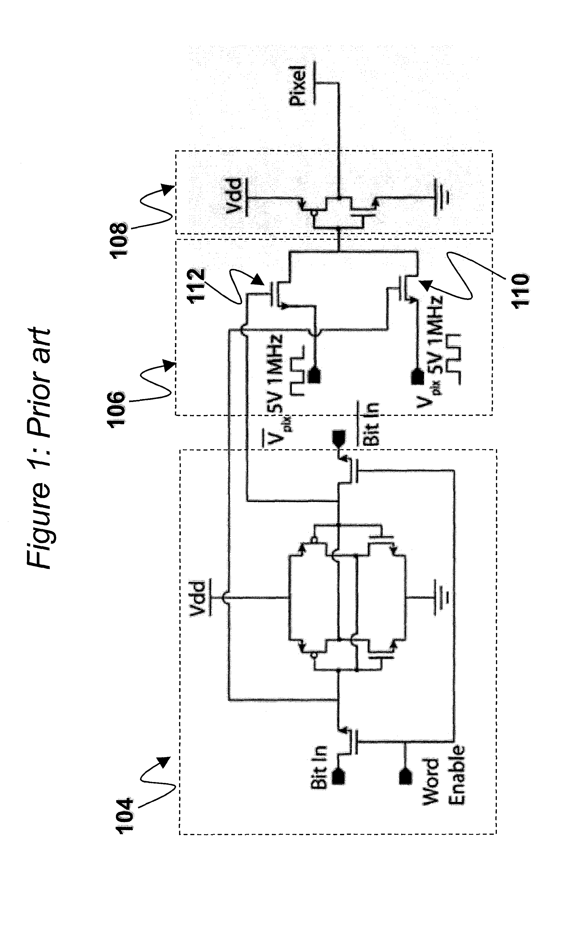
LC displays generally require that the voltage across the liquid crystal should be alternated (“inversion”) since the application of a DC field has deleterious effects for the LC material.
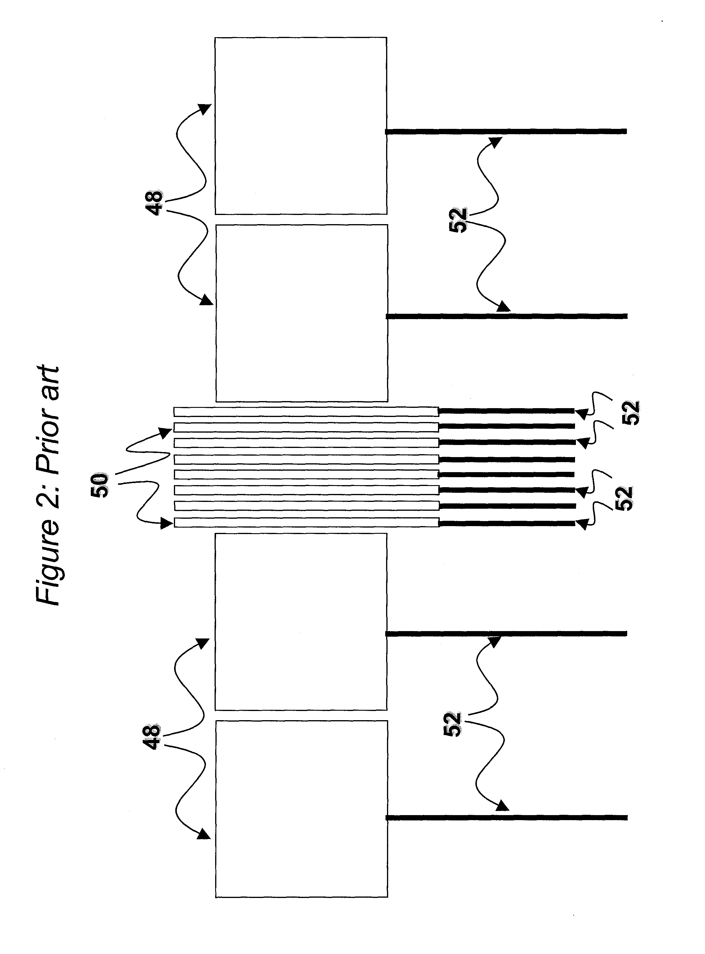
A notable disadvantage of such passive architectures for implementing EWOD and / or DEP is that a separate electrical connecting wire (e.g. 52) must be made to each individual electrode.
The total number of individually controllable elements within an array is thus limited by the number of electrical inputs to the device.
This makes large arrays impractical to implement.

Method used


Image

  • Active matrix device for fluid control by electro-wetting and dielectrophoresis and method of driving
  • Active matrix device for fluid control by electro-wetting and dielectrophoresis and method of driving
  • Active matrix device for fluid control by electro-wetting and dielectrophoresis and method of driving

Examples


Embodiment Construction

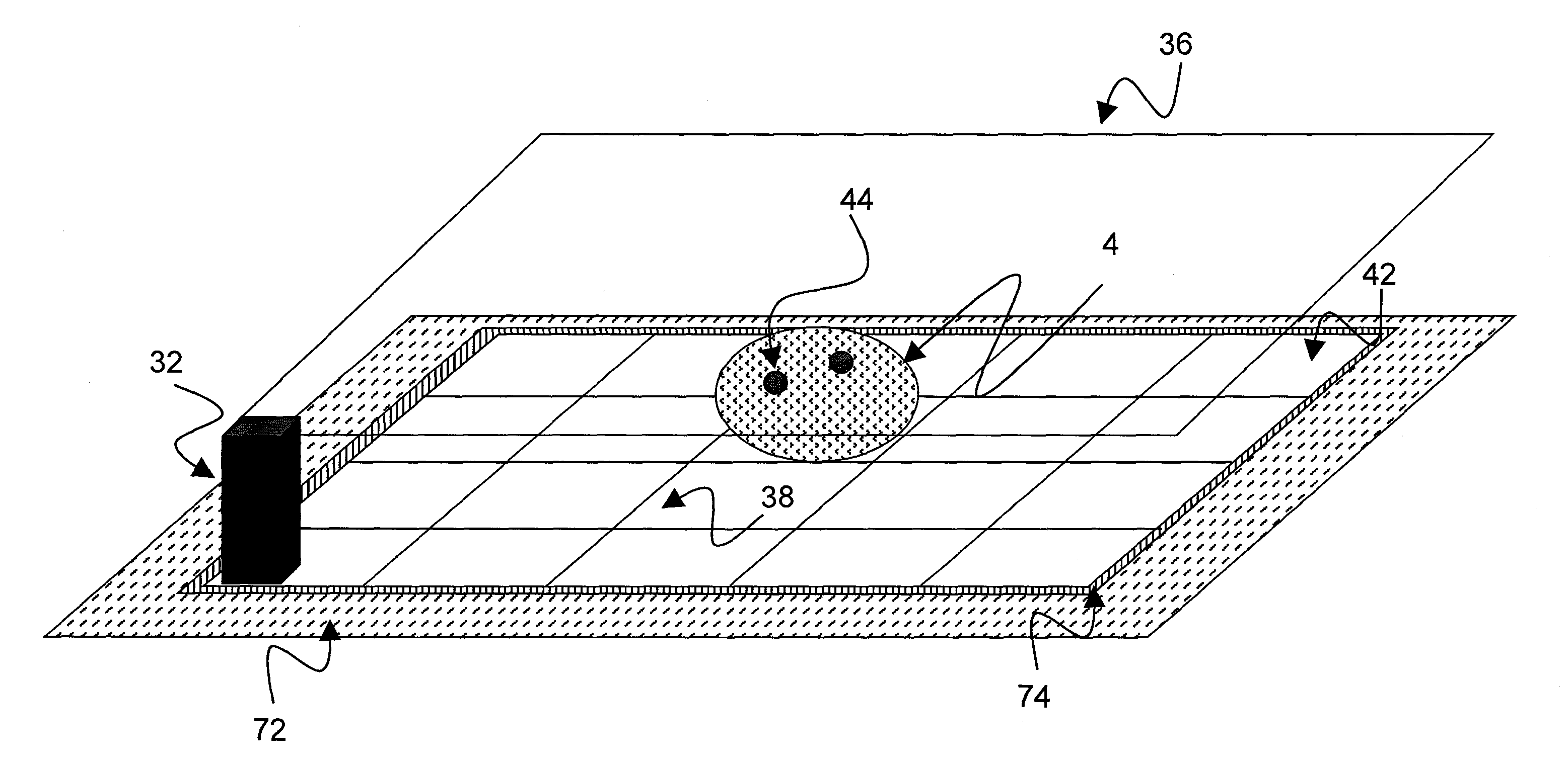
[0112]Referring to FIG. 3, shown is a droplet microfluidic device in accordance with an exemplary embodiment of the present invention. The droplet microfluidic device is an active matrix device with the capability of manipulating fluids by both EWOD and by DEP. The device is further capable of manipulating droplets by EWOD in one part of the array and at the same time manipulating droplets by DEP in another part of the array. The device is also reconfigurable such that a droplet in a given part of the array can be manipulated by EWOD at one time and by DEP at another time.

[0113]The droplet microfluidic device has a lower substrate 72 with thin film electronics 74 disposed upon the substrate 72. The thin film electronics 74 are arranged to drive array element electrodes, e.g. 38. A plurality of array element electrodes 38 are arranged in an electrode array 42, having M×N elements where M and N may be any number. In the exemplary embodiments herein, M and N are both equal to or greate...


PUM

PropertyMeasurementUnit
drive frequenciesaaaaaaaaaa
frequencyaaaaaaaaaa
EWOD actuation voltagesaaaaaaaaaa

Abstract

A microfluidic device includes a plurality of array elements configured to manipulate one or more droplets of fluid on an array, each of the array elements including a top substrate electrode and a drive electrode between which the one or more droplets may be positioned, the top substrate electrode being formed on a top substrate, and the drive electrode being formed on a lower substrate; and active matrix drive circuitry arranged to provide drive signals to the top substrate and drive electrodes of the plurality of array elements to manipulate the one or more droplets among the plurality of array elements. With respect to one or more of the array elements the active matrix drive circuitry is configured to provide the drive signals to the top substrate and drive electrodes to selectively manipulate the one or more droplets within the array element both by Electro-wetting-on-Dielectric (EWOD) and by Dielectrophoresis (DEP).

Description

TECHNICAL FIELD[0001]The present invention relates to active matrix arrays and elements thereof. In a particular aspect, the present invention relates to digital microfluidics, and more specifically to Active Matrix Electro-wetting-On-Dielectric (AM-EWOD). Electro-wetting-On-Dielectric (EWOD) is a known technique for manipulating droplets of fluid on an array. Active Matrix EWOD (AM-EWOD) refers to implementation of EWOD in an active matrix array, for example by using thin film transistors (TFTs). The invention further relates to methods of driving such a device.BACKGROUND ART[0002]Electro-wetting on dielectric (EWOD) is a well known technique for manipulating droplets of fluid by application of an electric field. It is thus a candidate technology for digital microfluidics for lab-on-a-chip technology. An introduction to the basic principles of the technology can be found in “Digital microfluidics: is a true lab-on-a-chip possible?”, R. B. Fair, Microfluid Nanofluid (2007) 3:245-281...

Claims


Application Information

Patent Timeline
Patent Type & Authority Applications(United States)
IPC IPC(8): G01N27/26
CPCB01L3/502784B01L2400/0427B01L2400/0424
Inventor HADWEN, BENJAMIN JAMESJOHN, GARETHZEBEDEE, PATRICK
Owner SHARP KK
Learn More