
Materials for Battery Electrolytes and Methods for Use

a battery electrolyte and material technology, applied in the field of battery electrolyte, can solve the problems of severe electrolyte decomposition in the battery, affecting both the performance and safety of the battery, and conventional electrolyte cannot be operated at high voltage, so as to facilitate the flow of curren

Inactive Publication Date: 2013-03-07
ASAHI KASEI KK
View PDF1 Cites 7 Cited by
  • Summary
  • Abstract
  • Description
  • Claims
  • Application Information

AI Technical Summary

Benefits of technology

The invention is about a new type of electrolyte solution for high voltage batteries that is stable at high temperatures and voltages. This solution can be used to form batteries for various applications such as electronics, vehicles, tools, and space. Embodiments of the invention can also include methods for stabilizing certain additives in the electrolyte. The technical effect of this invention is to improve the performance and reliability of high voltage batteries.

Problems solved by technology

Unfortunately, these conventional electrolytes typically cannot be operated at high voltages, since they are unstable above 4.5 V or other high voltages.
At high voltages, conventional electrolytes can decompose, for example, by catalytic oxidation in the presence of cathode materials, to produce undesirable products that affect both the performance and safety of a battery.
However, these cathode materials also have redox potentials greater than 4.5 V, allowing for operation of the battery at higher voltages but also possibly causing severe electrolyte decomposition in the battery.
Another problem with both organic carbonate-based electrolytes and other classes of electrolytes is chemical stability at elevated temperatures.
Even at low voltages, elevated temperatures can cause conventional electrolytes to decompose, for example, by catalytic oxidation in the presence of cathode materials, to produce undesirable products that affect both performance and safety of a battery.

Method used


Image

  • Materials for Battery Electrolytes and Methods for Use
  • Materials for Battery Electrolytes and Methods for Use
  • Materials for Battery Electrolytes and Methods for Use

Examples


example 1

Methodology for Formation and Characterization of Battery Cells Including Stabilizing Additives

[0225]Battery cells were formed in a high purity argon filled glove box (M-Braun, O2 and humidity content 4 cathode material (Li(1-x): Co(1-y-z): Fey: Tiz: (PO4)(1-a)) were mixed in 1-methyl-2-pyrrolidinone (Sigma Aldrich), and the resulting slurry was deposited on an aluminum current collector and dried to form a composite cathode film. A lithium or graphite anode was used. In case of a graphite anode, a graphitic carbon (mesocarbon microbeads or MCMB) was mixed with poly(vinylidene fluoride) (Sigma Aldrich), carbon black (Super P Li, TIMCAL), using 1-methyl-2-pyrrolidinone (Sigma Aldrich) as a solvent, and the resulting slurry was deposited on a copper current collector and dried to form a composite anode film. Each battery cell including the composite cathode film, a Millipore glass fiber or a polypropylene separator, and the lithium or graphite anode was assembled in a coin cell-type a...

example 2

[0226]Characterization of Battery Cell Including Stabilizing Additive

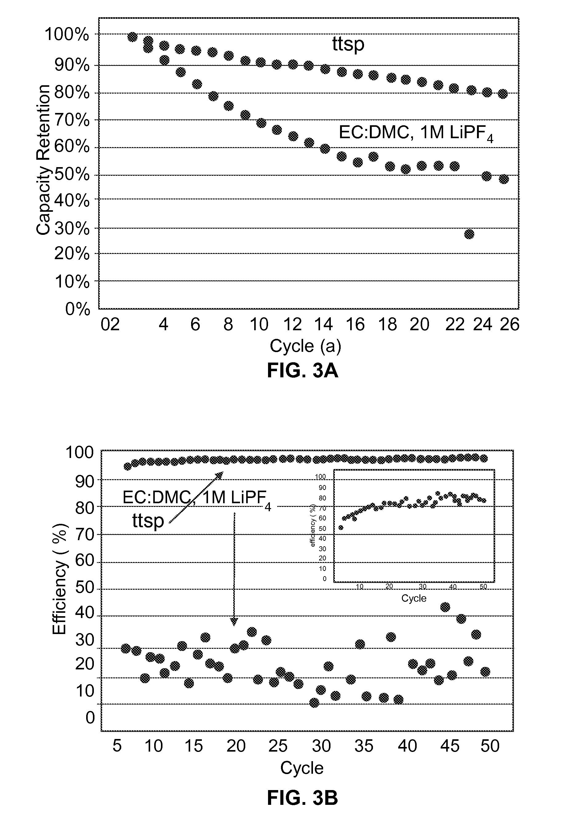
[0227]Using the methodology of Example 1, performance characteristics were measured for a test battery cell including about 10 wt. % of tris(trimethylsilyl) phosphate as a stabilizing additive (labeled as “ttsp”) dispersed in a conventional electrolyte (ethylene carbonate, dimethyl carbonate, and 1M LiPF6) and for a control battery cell including the conventional electrolyte but without the stabilizing additive (labeled as “EC / DMC, 1M LiPF6”). Each of the test battery cell and the control battery cell included a doped LiCoPO4 cathode material (Li(1-x)Co(1-y-z): Fey: Tiz: (PO4)(1-a). FIG. 3A (top) compares capacity retention with and without the stabilizing additive over several cycles, expressed in terms of a percentage of an initial specific capacity upon discharge retained at a particular cycle. As can be appreciated, the inclusion of the stabilizing additive improved cycle life, retaining about 78% of the initia...

example 3

[0228]Characterization of Battery Cell Including Stabilizing Additive

[0229]Using the methodology of Example 1, performance characteristics were measured for a test battery cell including tris(trimethylsilyl) phosphate as a stabilizing additive (labeled as “ttsp”) dispersed in a conventional electrolyte (ethylene carbonate, ethyl methyl carbonate, and 1M LiPF6) and for a control battery cell including the conventional electrolyte but without the stabilizing additive (labeled as “EC:EMC, 1M LiPF6”). Each of the test battery cell and the control battery cell included a doped LiCoPO4 cathode material (Li(1-x): Co(1-y-z): Fey: Tiz: (PO4)(1-a), and was cycled between about 2 V to about 4.95 V at a current of about 150 mA / g and at room temperature (25° C.). FIG. 4 compares capacity retention with and without the stabilizing additive over several cycles, expressed in terms of a percentage of an initial specific capacity upon discharge retained at a particular cycle. As can be appreciated, t...


PUM


Abstract

Described herein are materials for use in electrolytes that provide a number of desirable characteristics when implemented within batteries, such as high stability during battery cycling up to high temperatures high voltages, high discharge capacity, high coulombic efficiency, and excellent retention of discharge capacity and coulombic efficiency over several cycles of charging and discharging. In some embodiments, a high voltage electrolyte includes a base electrolyte and a set of additive compounds, which impart these desirable performance characteristics.

Description

[0001]This application is a continuation-in-part of pending U.S. application Ser. No. 13 / 459,702 filed Apr. 30, 2012 entitled “Materials for Battery Electrolytes and Methods for Use,” which in turn claims priority to each of the following applications: U.S. Provisional Application No. 61 / 495,318 filed Jun. 9, 2011 entitled “Battery Electrolytes for High Voltage Cathode Materials”; U.S. Provisional Application No. 61 / 543,262 filed Oct. 4, 2011 entitled “Battery Electrolytes for High Voltage Cathode Materials”; and U.S. Provisional Application No. 61 / 597,509 filed Feb. 10, 2012 entitled “Battery Electrolytes for High Voltage Cathode Materials.” This application claims priority to and the benefit of each of the above applications and each of the above applications is incorporated herein by reference.BACKGROUND OF THE INVENTION[0002]The invention relates generally to battery electrolytes. More particularly, the invention relates to battery electrolytes to improve stability of batteries,...

Claims


Application Information

Patent Timeline
IPC IPC(8): H01M10/056
CPCH01M10/0525Y02T10/7011Y02E60/122H01M10/0567Y02E60/10Y02T10/70
Inventor BHAT, VINAY V.CHENG, GANGKAYE, STEVEN S.LI, BINOLUGBILE, RISAYANG, JEN-HSIEN
Owner ASAHI KASEI KK
Learn More