
Sensor and method of producing a sensor

a sensor and sensor technology, applied in the field of sensors and a production method of sensors, can solve the problems not being able to suppress the predominant low-frequency components, and not being able to solve the problem of reducing the price of devices,

Inactive Publication Date: 2013-03-07
FRAUNHOFER GESELLSCHAFT ZUR FOERDERUNG DER ANGEWANDTEN FORSCHUNG EV
View PDF2 Cites 10 Cited by
  • Summary
  • Abstract
  • Description
  • Claims
  • Application Information

AI Technical Summary

Benefits of technology

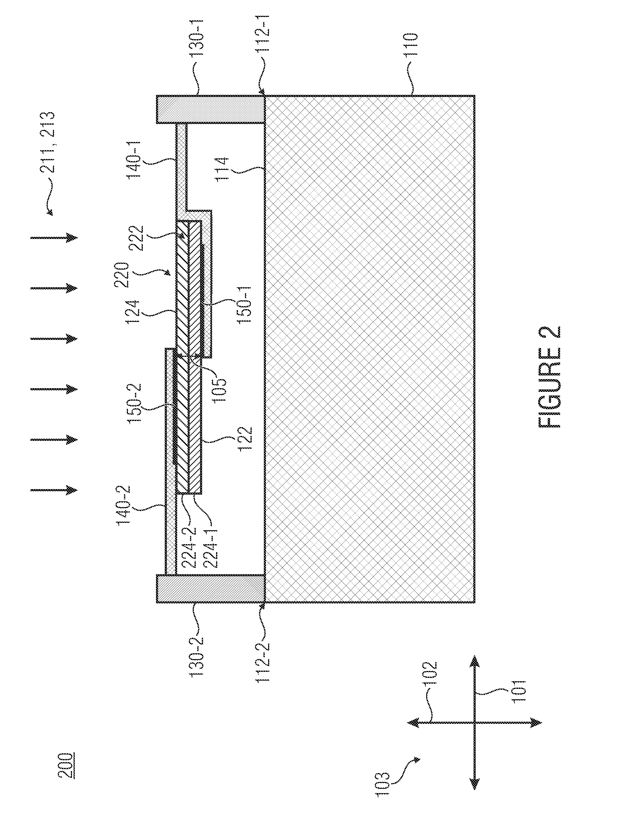
The present invention provides an improved method of utilizing membrane space and increasing sensitivity and precision. By using a first and second support structure that contacts the membrane from both sides, the membrane can be suspended and electrically connected to the substrate, resulting in improved area utilization and sensitivity, as well as more flexible or precise readout. Additionally, the membrane may include a vertical bipolar transistor or field-effect transistor to amplify captured signals directly at the membrane or sensor element. This reduces the need for a readout circuit located within the substrate between the first and second spacers.

Problems solved by technology

If the change in the resistance of the material which is induced by the change in temperature is smaller than the noise of the electric parameters, it will no longer be resolved.
This approach has the decisive disadvantage that it cannot accommodate the increasing desire for miniaturization and, thus, reduction in the price of the devices.
This is a serious problem in that the integrative readout circuits (low pass) typically used are not suited to suppress the predominant low-frequency components of said noise.
However, this advantage typically is at the expense of a heavily reduced dependence of the resistance on the temperature.
However, integration of such thermally insulated sensors in a CMOS process involves quite some effort.
The initially used approach of producing the insulated diodes directly in the CMOS wafer by suitable undercutting etching processes has the disadvantage of requiring a very large amount of surface area without combining useful insulation and absorption properties.
Moreover, in this manner, the membrane cannot be contacted laterally only, but also vertically.

Method used


Image

  • Sensor and method of producing a sensor
  • Sensor and method of producing a sensor
  • Sensor and method of producing a sensor

Examples


Embodiment Construction

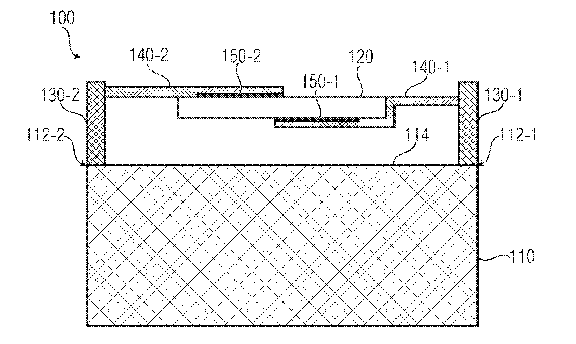
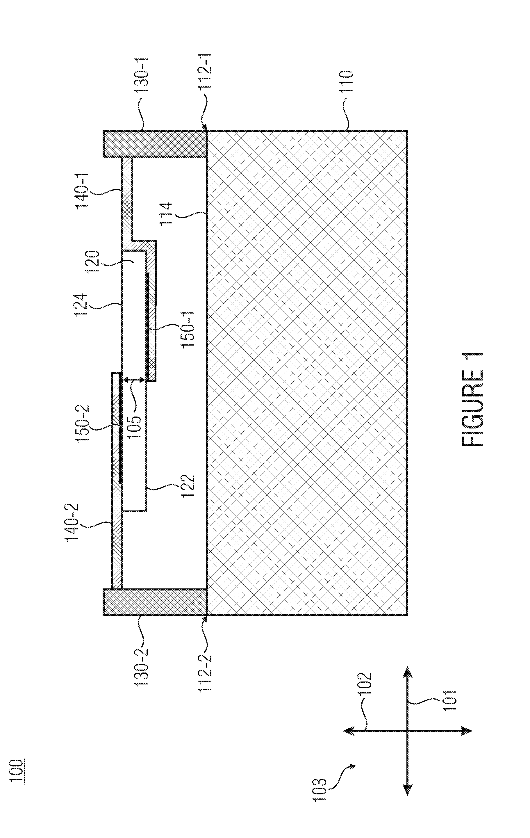
[0028]Before the present invention will be explained in more detail below by means of the figures, it shall be pointed out that in the embodiments presented in the following, elements which are identical or identical in function are provided with the identical reference numerals in the figures. Therefore, descriptions of elements having identical reference numerals are mutually exchangeable and / or mutually applicable in the various embodiments.

[0029]FIG. 1 shows a cross-sectional view of a sensor 100 in accordance with an embodiment of the present invention. As is shown in FIG. 1, the sensor 100 comprises a substrate 110, a membrane 120, first and second spacers 130-1, 130-2, a first support structure 140-1 and a second support structure 140-2. Here, the first and second spacers 130-1, 130-2 are arranged on the substrate 110. In the sensor 100 shown in FIG. 1, the first support structure 140-1 is supported, laterally next to the membrane 120, by the first spacer 130-1 and contacts a...


PUM


Abstract

A sensor includes a substrate, a membrane, first and second spacers arranged on the substrate, a first support structure which is supported, laterally next to the membrane, by the first spacer and contacts a first electrode of a first main side of the membrane which faces the substrate, and a second support structure which is supported, laterally next to the membrane, by the second spacer and contacts a second electrode on a second main side of the membrane which is opposite the first main side, so that the membrane is suspended via the first and second spacers and is electrically connected to contact areas of the substrate.

Description

CROSS-REFERENCE TO RELATED APPLICATIONS[0001]This application claims priority from German Patent Application No. 102011081641.0 which was filed on Aug. 26, 2011, and is incorporated herein in its entirety by reference.TECHNICAL FIELD[0002]Embodiments of the invention relate to a sensor and a method of producing a sensor. Further embodiments of the invention relate to contacting of monocrystalline optical sensors.BACKGROUND OF THE INVENTION[0003]Detection of infrared radiation is becoming increasingly important in many different fields. For the automobile industry, this importance lies in achieving increased safety for, e.g., pedestrians, who can be made visible with infrared sensors even in dark surroundings. If an automatic brake system is coupled to a sensor system, accidents may be avoided, or their impacts may at least be attenuated. Further applications of infrared sensors include, e.g., inspecting technical equipment (e.g. electric lines or even printed circuit boards) or buil...

Claims


Application Information

Patent Timeline
IPC IPC(8): H01L31/036H01L31/18H01L31/0376
CPCG01J5/046G01J5/024G01J5/023G01J5/0225
Inventor VOGT, HOLGERWEILER, DIRKKROPELNICKI, PIOTR
Owner FRAUNHOFER GESELLSCHAFT ZUR FOERDERUNG DER ANGEWANDTEN FORSCHUNG EV
Learn More