Welding system and method

a welding system and welding technology, applied in the field of welding processes, can solve the problems of humping or lack of fusion of weld beads, insufficient power density of typical arcs, and difficulty in deep weld formation

Inactive Publication Date: 2013-03-07
GENERAL ELECTRIC CO
View PDF28 Cites 14 Cited by
  • Summary
  • Abstract
  • Description
  • Claims
  • Application Information

AI Technical Summary

Benefits of technology

[0013]FIG. 2 is a flow chart showing an exemplary process for welding pieces

Problems solved by technology

Further still, as thermal conductivity of the weld material decreases, formation of deep welds becomes more difficult.
Attempts to join pieces comprising alloys having relatively high temperature melting points such as the above-cited materials, wherein the thickness of the pieces to be joined is at least approximately 0.2 inches or at a common thickness of 0.25 inches, at commercially acceptable speeds (such as at least approximately twenty inches per minute or at a more preferred rate of sixty inches per minute or even at rates as high as one hundred inches per minute) have presented significant challenges.
More precisely, while experience has shown that arc welding techniques can generate a relatively large weld pool, the relatively low power density (e.g., approximately 104 watts per square centimeter) of typical arcs is generally insufficient to enable the molten material to penetrate to sufficient depths within the pieces at moderate to high welding speeds (i.e., at least about thirty to seventy inches per minute).
Attempts to employ faster weld speeds have resulted in humping or lack of fusion of the weld bead.
Attempts to use lasers to solve these problems have achieved only limited success.
For example, while lasers have been able to achieve increased weld

Method used


Image

  • Welding system and method
  • Welding system and method
  • Welding system and method

Examples


Embodiment Construction

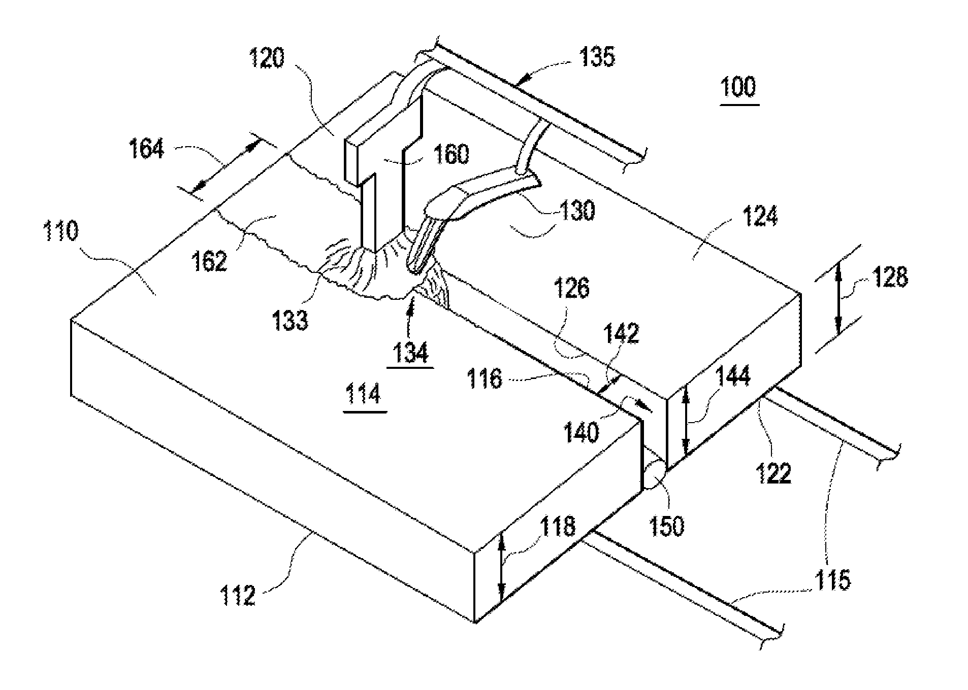
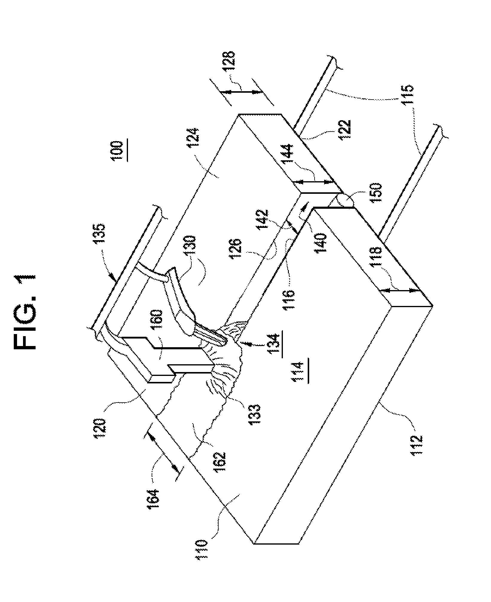
[0018]Referring now to the drawings, in which like numerals refer to like elements throughout the several views, FIG. 1 shows an exemplary welding system using a combination of welding techniques. As shown in FIG. 1, a welding system 100 for joining two or more pieces 110, 120 includes an arc welder 160 that is positioned and configured to follow a gap 140 and to transfer material to the vicinity of the gap 140 so as to create an initial weld pool 133 of a desired width in the vicinity of a gap 140. To accomplish this, arc welder 160 is positioned so as to follow the gap 140 as an electrical arc from arc welder 160 transfers material to the vicinity of the gap 140. In an exemplary embodiment, arc welder 160 forms initial weld pool 133 by transferring weld material from a consumable electrode. The initial weld pool 133 traverses the gap and rests upon the two or more pieces 110, 120.

[0019]A laser welder 130 is positioned and configured to project a laser beam onto the initial weld po...


PUM

PropertyMeasurementUnit
Thicknessaaaaaaaaaa
Diameteraaaaaaaaaa
Speedaaaaaaaaaa

Abstract

A welding system comprises pieces positioned to form a gap, a filler positioned in the gap, an arc welder positioned and configured to follow the gap and transfer melted material to the vicinity of the gap to create an initial weld pool, and a laser welder positioned and configured to project a beam through the initial weld pool adjacent to the gap to melt a portion of the filler, creating an enhanced weld pool and helping it to fill the gap. A welding method comprises fixing pieces to define a gap, positioning a filler in the gap, applying an electrical arc to at least one of the pieces so as to transfer melted material to the vicinity of the gap and thereby create an initial weld pool, and projecting a laser beam through the initial weld pool adjacent to the gap to melt a portion of the filler.

Description

BACKGROUND OF THE INVENTION[0001]The subject matter disclosed herein relates generally to welding processes and more specifically systems and methods for welding using hybrid welding techniques.[0002]In today's world, a number of welding techniques are known for joining two or more pieces of metal. Typically, one or more welding techniques are used to apply energy so as to create a weld pool comprising molten weld material that traverses a joint or seam between the pieces that are to be joined. As the molten material solidifies, a weld is created joining the pieces. Common techniques for applying energy to create the weld pool use laser welders or electrical arc welders. For example, in laser welding, a laser beam is applied to the pieces to melt a portion pieces, thereby creating a weld pool. In arc welding, an electrical arc is established between the pieces and an electrode. In gas metal arc welding (GMAW), the arc melts the consumable electrode and carries the melted material to...

Claims


Application Information

Patent Timeline
IPC IPC(8): B23K26/00B23K9/12B23K26/08B23K9/00
CPCB23K26/1429B23K26/26B23K2201/001B23K28/02B23K26/285B23K26/282B23K26/348B23K2101/001
Inventor LIN, DECHAOCUI, YANKOTTILINGAM, SRIKANTH CHANDRUDU
Owner GENERAL ELECTRIC CO
Why Eureka
Try Eureka