
Video Analysis Using Segmentation Gain by Area

a video analysis and gain technology, applied in the field of video monitoring and interpretation, can solve the problems of affecting the usability of information, affecting the acuity of certain areas, and reducing the fatigue of operators in a cctv system, so as to improve the segmentation of mixed objects, improve the acuity of certain areas, and reduce nois

Active Publication Date: 2007-11-15
CHECKVIDEO
View PDF20 Cites 17 Cited by
  • Summary
  • Abstract
  • Description
  • Claims
  • Application Information

AI Technical Summary

Benefits of technology

This approach enhances the system's ability to capture and analyze video data effectively, improving discrimination between subjects and activities, and providing better characterization of movement directions, thereby enhancing the overall visual acuity and accuracy of video security systems.

Problems solved by technology

As the video may be taken by video cameras in any of many possible locations and under conditions subject to variation beyond the control of the system, the captured video can include useless information such as visible “noise” which, upon segmentation of images together with such noise, interferes with usable information or detracts from or degrades video data useful to the system.
The Perceptrak system includes six primary software elements, each of which performs a unique function within the operation of such system to provide intelligent camera selection for operators, resulting in a marked decrease of operator fatigue in a CCTV system.
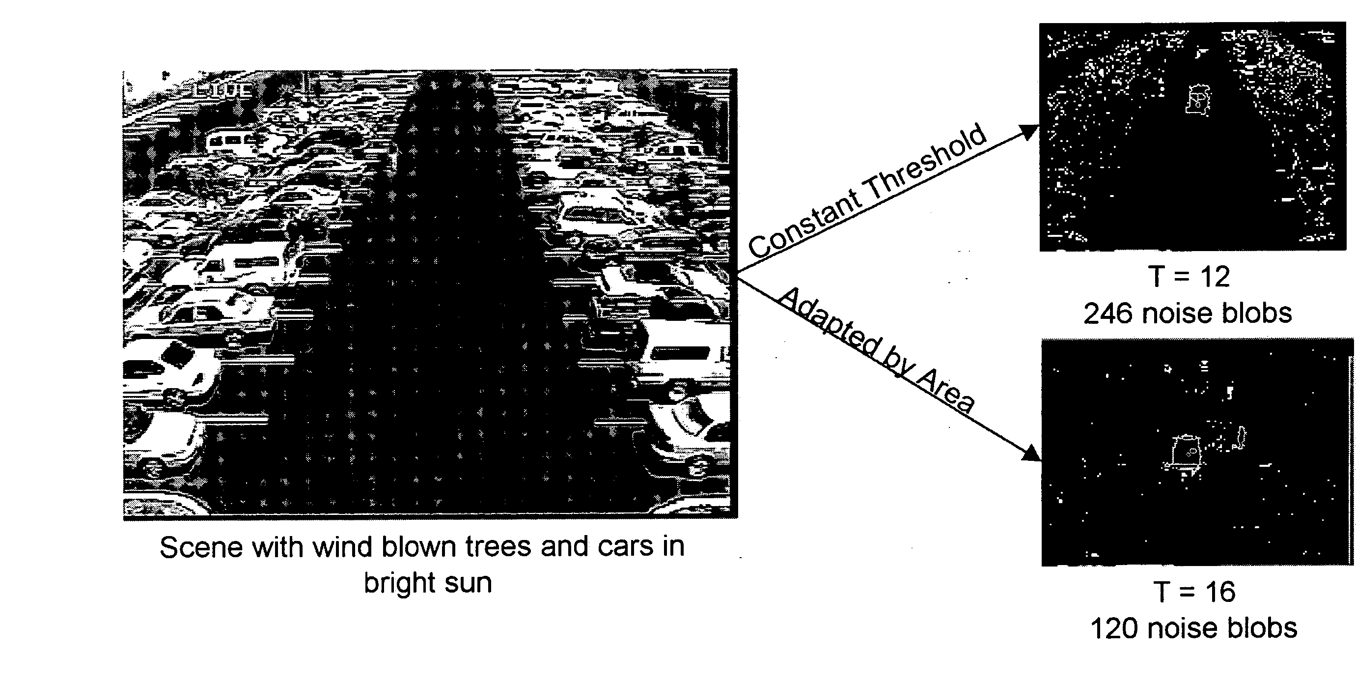
A difficulty has been realized in that segmentation gain can be very low in “quiet” (relatively noise-free) areas of the scene, but noise elsewhere in the image may have the result that subjects (such as people) within the image field are only partially segmented.
A difficulty exists in that changes in gain are controlled not only in response to objects in the captured video, which objects it is desired that the system segment, but also in response to light “noise.” Such visual noise degrades segmented images.
The noise thus interferes with getting segmented images of subject people within the scene.

Method used


Image

  • Video Analysis Using Segmentation Gain by Area
  • Video Analysis Using Segmentation Gain by Area
  • Video Analysis Using Segmentation Gain by Area

Examples


example 1

[0079] It is found in practice that the segmentation gain loop has been very stable with a single setting for the entire video scene. By comparison, at attempt to set segmentation gain for every pixel would certainly be unstable. Therefore, to maintain stability, and yet have the benefit of segmentation gain by area as herein described, the number of settings could be purposely limited to a predetermined number of value (such as 4, for example for illustrative purposes only). Further, the minimum area of the screen to have an independent gain setting will be limited to 1 / 64th of the screen, as an example for illustrative purposes. FIG. 2 illustrates the effect of an eight by eight grid of a scene to be analyzed as according to the Perceptrak system. Calculations will be generic to allow tuning the grid resolution. As according to that disclosure, to enable generic calculations, the number of grids will be determined by global variables SegGridsHigh and SegGridsWide. For this example...

example 2

[0083] This example illustrates the presently disclosed method of tracking noise by location. Reference again may be had to other examples setting forth representative lines of code of Visual Basic useful in implementing the present methodology and system configuration.

[0084] A new UDT (in the context of Visual Basic a “User Defined Type” is defined to hold data about noise in grids, (NoiseBySegGridType), with three longs (i.e., a 32 bit integer), thus:

InActiveMask   / / set to 1 at start up if in the active area of themaskNoiseBlobThisPeriod / / Cum. NoiseBlobs since lastCalcSegmentationValuesNoiseBlobsLastPeriod / / NoiseBlobs used in lastCalcSegmentationValues

[0085] The NoiseBlobsLastPeriod element is reserved for the part of a PID loop. A new global UDT (NoiseBySegGrid) is allocated and used to accumulate the number of noise blobs for each map element. NoiseBySegGrid is allocated as SegGridsHigh*SegGridsWide. In the LabelBlobs function where Noise Blobs in incremented, the element o...

example 3

[0090] The example typifies calculation of gain adjustment. Reference may be had again to other examples setting forth representative lines of code of Visual Basic useful in implementing the present methodology and system configuration.

[0091] Gain adjustment by area is based on a gain figure for DeltaSegmentation per DeltalNoise. The variable is named “DeltaSegGain” and the default value is to be set by test. A DeltaSegGain of 0.5 indicates an adjustment of one for each two noise blobs difference between the area under consideration and the screen average, where:

GainAdjustment=DeltaSegGain*(GridNoise−AverageScreenNoise)

and where:

a higher GainAdjustment means a lower gain for the Grid;

and where:

AverageScreenNoise is adjusted for comparison with GridNoise.

[0092] For an example with 64 grids, the total number of noise blobs in the 1 / 64th grid is to be compared to the total number of noise blobs in the scene divided by 64.

[0093] For each background maintenance operation, a P...


PUM


Abstract

Video segmentation methods and systems are described wherein scene images of subjects and background are captured by video and are automatically segmented according to subject content, as by system determination of the nature of subjects. Segmentation transformations of an original background and foreground images in the scenes are provided as a terrain map. Automatic segmentation threshold adaptation is based on measuring the segmentation noise while holding the number count of noise blobs constant, whereby to achieve noise-adaptive segmentation gain. Automatic threshold adaptation within multiple areas of the scene results in different possible thresholds in different areas based on the amount of segmentation noise in each area. Segmentation is improved accordingly.

Description

CROSS-REFERENCE TO RELATED APPLICATION [0001] This application is a continuation of application Ser. No. 11 / 088,308, filed Mar. 24, 2005, which is being issued as U.S. Pat. No. 7,218,756 on May 15, 2007, entitled VIDEO ANALYSIS USING SEGMENTATION GAIN BY AREA, which claims the priority of U.S. provisional patent application No. 60 / 555,817, filed Mar. 24, 2004, entitled IMPROVEMENT IN VIDEO ANALYSIS USING SEGMENTATION GAIN BY AREA, both incorporated herein by reference.BACKGROUND OF THE INVENTION [0002] 1. Field of the Invention [0003] The invention relates to video monitoring and interpretation, as by software-aided methodology, and more particularly, to a system and method for improving the utility of video images in systems handling video, such as for system-interpreted analysis of video images for security purposes, and for many other purposes. [0004] 2. Description of the Known Art [0005] There has been developed a system in accordance with U.S. patent application Ser. No. 09 / 77...

Claims


Application Information

Patent Timeline
Patent Type & Authority Applications(United States)
IPC IPC(8): G06K9/00G06T5/00G06V10/30G06V20/40G06V40/10
CPCG06K9/00362G06K9/00711G06K9/40G06K2209/23G06T7/0081G06T2207/30236G06T2207/10016G06T2207/20012G06T2207/20144G06T2207/20148G06T7/0097G06T7/11G06T7/174G06T7/194G06T7/136G06V40/10G06V20/40G06V10/30G06V2201/08G06T7/40
Inventor GAROUTTE, MAURICE V.
Owner CHECKVIDEO
Learn More