
Guide pad

a guide pad and guide pad technology, applied in the field of guide pads, can solve the problems of cracking of the guide pad, high friction between the guide pad and the borehole wall, and high temperatur

Active Publication Date: 2013-02-28
BOTEK PRAEZISIONSBOHRTECHNIK GMBH
View PDF2 Cites 27 Cited by
  • Summary
  • Abstract
  • Description
  • Claims
  • Application Information

AI Technical Summary

Benefits of technology

This patent discusses the importance of optimal lubrication for a guide pad system. It suggests that lubricating grooves should be small in width compared to the guide pad. It also states that lubricating grooves should only have a depth of 0.1 mm to 1.5 mm. Additionally, the patent states that using carbide or coating guide pads with a hard material layer can increase their lifespan.

Problems solved by technology

In the event of inadequate cooling and / or lubrication by the coolant lubricant, the friction between guide pad and borehole wall can be very high in this contact zone, whereby very high temperatures can occur.
A generally known problem, which is caused by the high temperatures, is cracking in the guide pads.
Breakouts or a fracture of the guide pad can thus occur, whereby the borehole surface can be damaged.
This damage can have the result that the workpiece must be reworked or is no longer usable.
This implementation does allow optimum coolant passage, however, sufficient lubrication in the region of the contact surfaces is not ensured to the full extent.
However, coolant lubricant can only reach the contact surfaces themselves with difficulty.

Method used


Image

  • Guide pad
  • Guide pad
  • Guide pad

Examples


Embodiment Construction

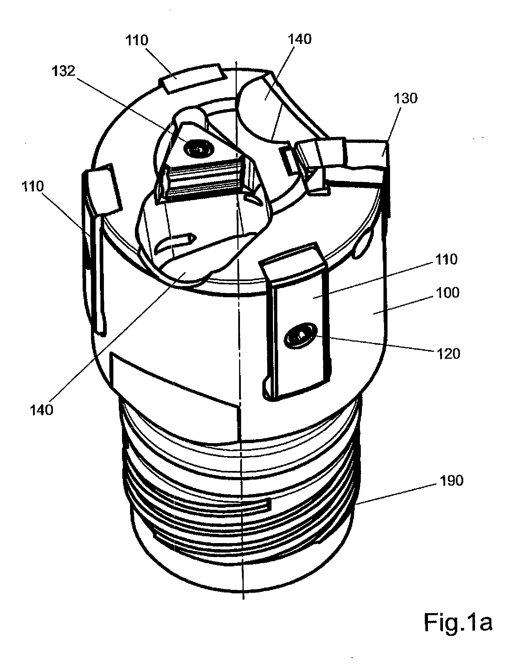
[0038]FIG. 1a shows an isometric view of a drilling head 100 for the so-called BTA drilling system, which is equipped with three replaceably fastened guide pads 110 according to the invention. The guide pads 110 are fastened on the drilling head 100 using screws 120, so that they can be turned over or replaced with new guide pads 110 after reaching their service life. The service life of the drilling head 100 can be a multiple of the service life of the guide pads 110.

[0039]Furthermore, two cutting plates 130, 132, which are replaceably fastened using screws, are arranged on the drilling head 100. The drilling head 100 has two openings 140, which are connected to an inner channel. The chips arising during the drilling are discharged via these openings 140 and the inner channel. At one end, the drilling head 100 is provided with a receptacle 190, using which it is connected to a drilling rod (not shown) in a way known per se. Both the number and arrangement of the cutting plates 130,...


PUM

PropertyMeasurementUnit
Angleaaaaaaaaaa
Angleaaaaaaaaaa
Depthaaaaaaaaaa

Abstract

A guide gib (500) for a deep drilling tool of a substantially rectangular shape with a longitudinal direction (L) and a width (B) and with at least one sliding surface (540) is characterized in that at least one lubricating groove, preferably a plurality of lubricating grooves (501, 502), is / are arranged at least in the region of a contact zone of the sliding surface.

Description

PRIOR ART[0001]The invention relates to a guide pad according to the species of independent Claim 1.[0002]Guide pads are fastened in a seat on a drilling head of a deep drilling tool. The fastening can be performed in a removable or replaceable manner (e.g., by screws) or also in a materially bonded manner (e.g., by soldering or gluing). A guide pad has at least one sliding surface, which is provided for the purpose of interacting with the borehole wall. The most typical systems in deep drilling are the single-flute gundrill system, the so-called BTA system (BTA=boring and trepanning association), also called the STS system (STS=single tube system), and the ejector system. VDI guideline VDI3210 gives an overview.[0003]In these deep drilling systems, a coolant lubricant is typically used, in order to lubricate and cool cutters and guide pads, on the one hand, and to flush the chips arising during the machining out of the borehole, on the other hand. Deep drilling tools are primarily ...

Claims


Application Information

Patent Timeline
IPC IPC(8): B23B41/02
CPCB23B51/0486Y10T408/5586B23B2251/56B23B2251/422B23B51/063B23B2229/04B23B2270/34
Inventor WENZELBURGER, KARL-HEINZWENZELBURGER, JUERGEN
Owner BOTEK PRAEZISIONSBOHRTECHNIK GMBH
Learn More