
Pulse-power apparatus and water treatment system for inhibiting scale formation and microorganism growth

Active Publication Date: 2013-02-28
ENVIRONMENTAL ENERGY TECH
View PDF10 Cites 11 Cited by
  • Summary
  • Abstract
  • Description
  • Claims
  • Application Information

AI Technical Summary

Benefits of technology

The present invention offers an affordable, efficient, and low-maintenance solution for removing scale and preventing the growth of harmful biotic organisms in small to medium size cooling systems. This alternative to chemical treatments helps to reduce the need for costly maintenance and downtime. The invention targets both scale and biological hazards, making it a comprehensive solution for keeping water systems clean and safe.

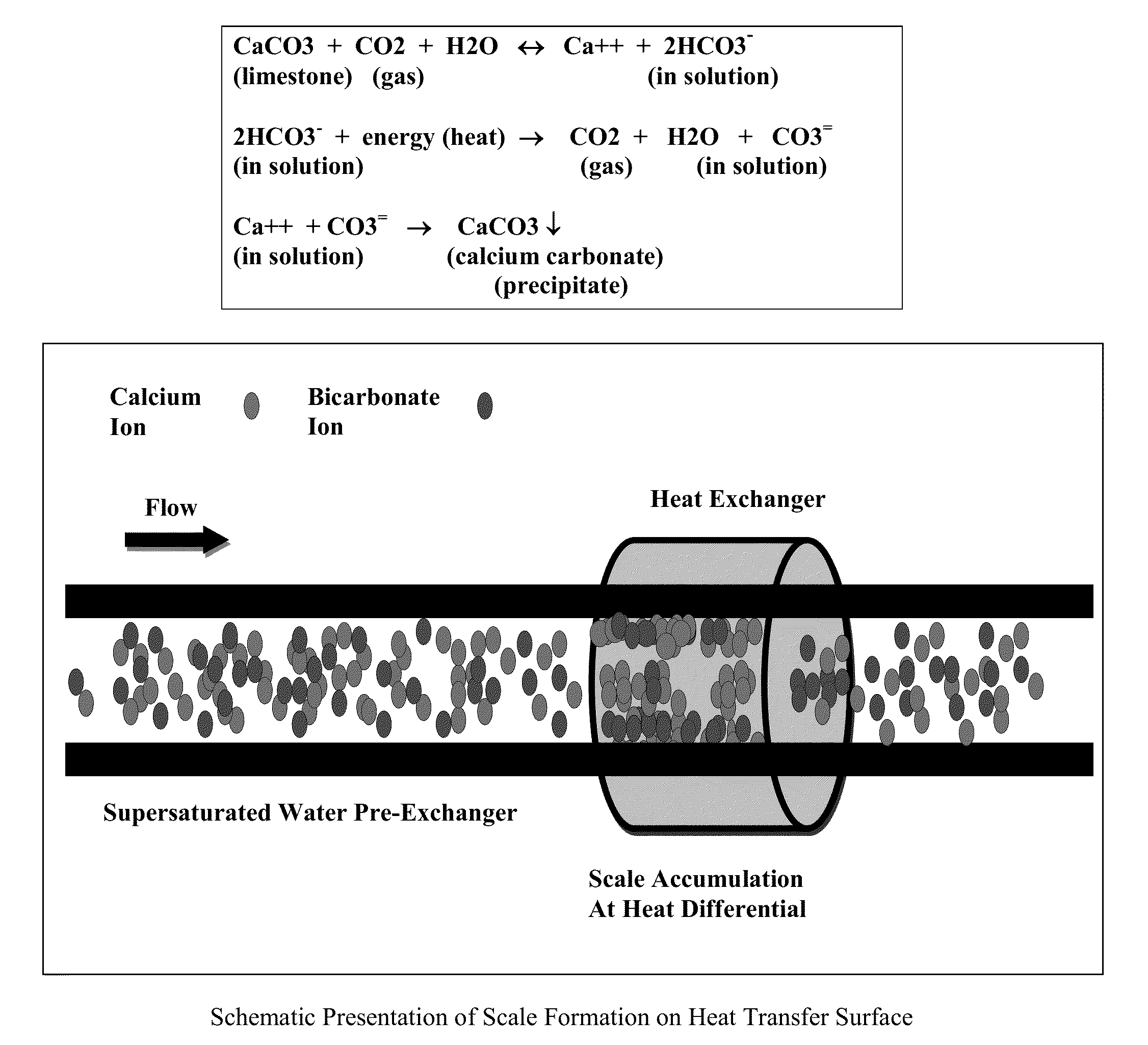
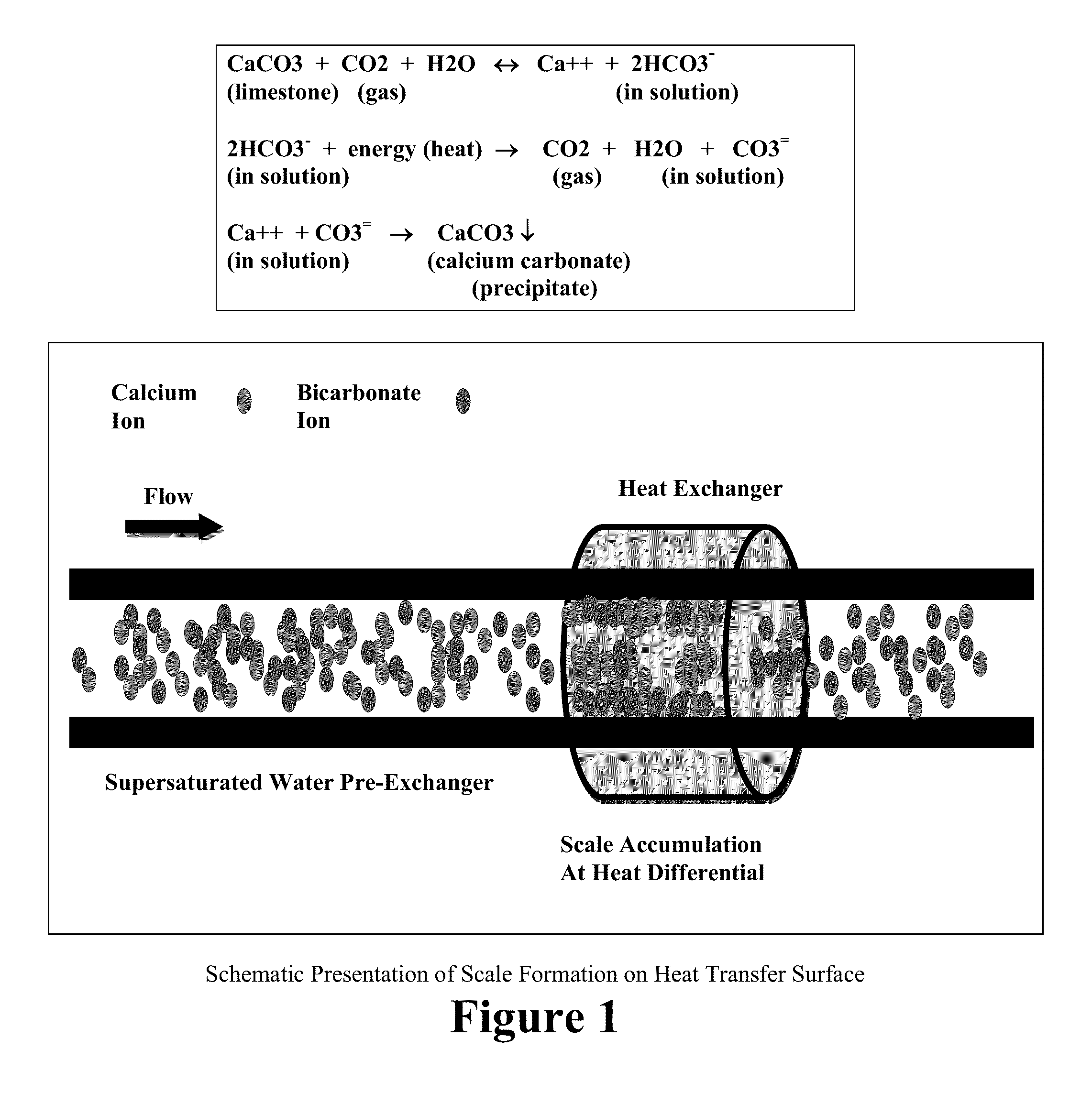
Problems solved by technology

In cooling towers, even if the water is soft, the water quickly becomes hard due to evaporation.
The precipitation of these ions occurs due to their having less solubility in hot water, thereby causing hard scale formation on heat transfer surfaces (shown schematically in FIG. 1), reducing their efficiency.
Generally, scales are removed using acid chemicals, which procedure shortens the life of the equipment.
In addition, chemicals in the concentrated form are often acute toxins, and their use is undesirable.
Further, unless chemicals are added at the right time and rate, the use of chemicals to remove scale can be ineffective.
Also, if improperly added to a system, chemicals may cause severe operational problems.
Unfortunately, these methods are mostly expensive and require heavy maintenance for proper operation.
However, as with the chemical treatment for scale formation, the use of chemicals to kill, treat, or prevent biofilm and microorganism growth in water systems is costly, requires maintenance, and presents safety issues.
While pulsed power water treatment systems have been described for use in treating scale and / or biofilm growth, these systems can be cumbersome to implement into existing water treatment systems, ineffective in treating both scale and biofilm, and / or require high voltage.

Method used


Image

  • Pulse-power apparatus and water treatment system for inhibiting scale formation and microorganism growth
  • Pulse-power apparatus and water treatment system for inhibiting scale formation and microorganism growth
  • Pulse-power apparatus and water treatment system for inhibiting scale formation and microorganism growth

Examples


example 1

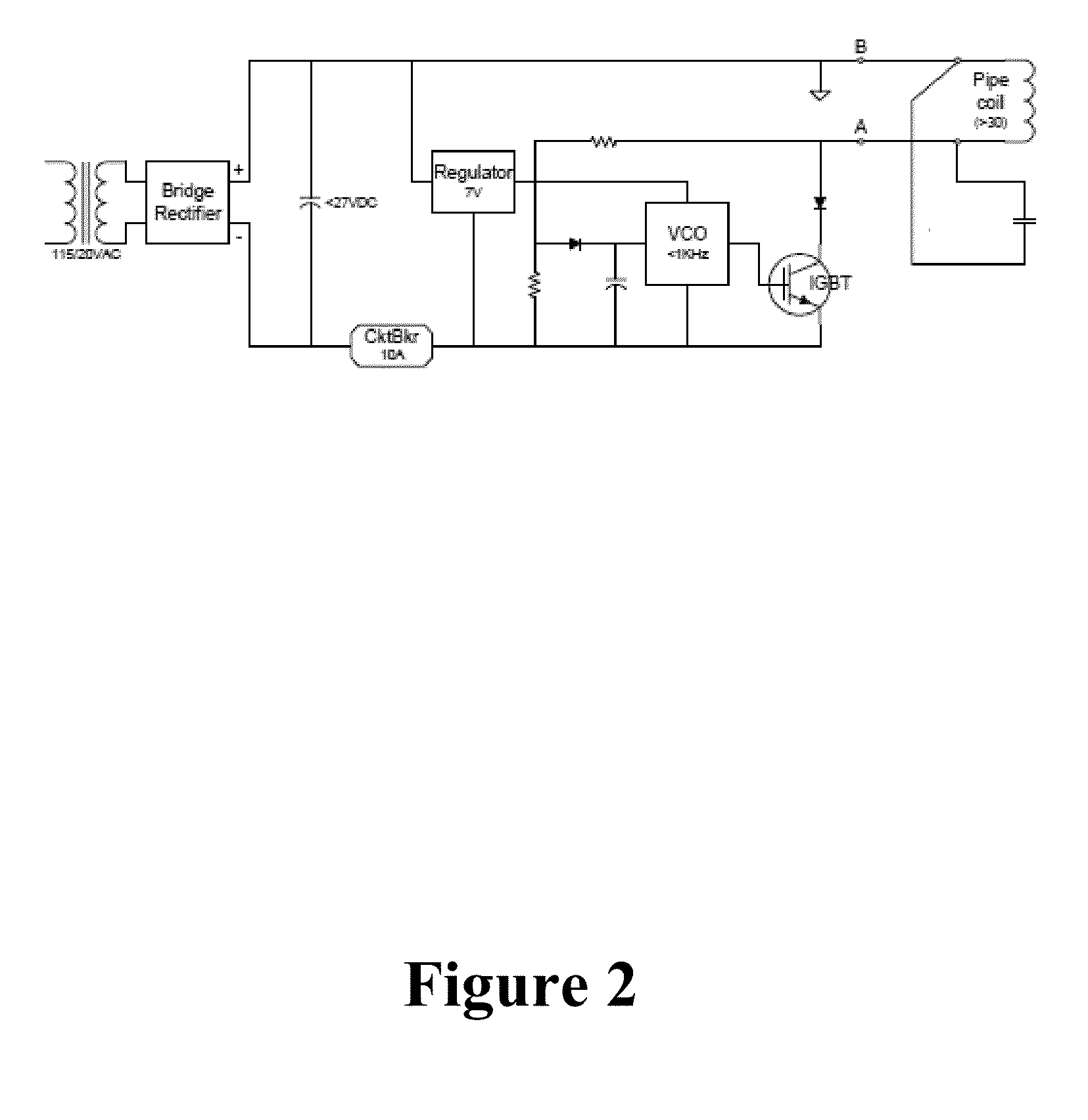
Pulse-Power Supply for Water Treatment

[0064]Described herein below and illustrated in the accompanying drawings are various embodiments of the apparatus and water treatment system of the present invention, as well as methods of making and using the apparatus and water treatment system of the present invention. While illustrative examples are provided herein, the present invention is not intended to be limited in scope to only the embodiments described herein.

[0065]In general, an electrical power supply for generating electrical fields that will control bio-matter (e.g., microorganisms such as bacteria) in chilled water cooling systems is more complex than one that just controls scale. Simple scale control has been done using fixed magnetic fields (DC) such as that of simple permanent magnets. Provided in this example is a description of one embodiment of the present invention relating to an inexpensive and easily installed scale and bio-matter control pulse system that draws less th...

example 2

Construction of an Apparatus for Treatment of Scale and Microorganisms

[0071]Below are general guidelines on how various embodiments of the apparatus and water treatment system of the present invention were prepared. With regard to the chamber, in using PVC (although steel or other metallic pipes ordinarily used in water systems can be used), it is generally recommended that all flush joints are primed and PVC cemented. All threaded joints can include the use of sealant to prevent leaking when the system is active. Besides this all pieces fit in the logical manner and should be left to completely dry and adhere before the coil is wrapped.

[0072]The coils can be wrapped flat and tight around the main shaft of the chamber. In exemplary embodiments (referred to as Gen0.0 and Gen0.1), the Gen0.0 system used 75 turns per coil on a 4″ pipe and Gen0.1 used 100 turns per coil on a 3.5″ pipe. Each coil was roughly 100′ of wire and can be considered the baseline for any new construction. Dual c...

example 3

Operating Parameters

[0074]In one exemplary embodiment of an apparatus of the present invention, various operating parameters were observed. After the power supply has been turned on and the internal breaker is not tripped and a signal can be produced on the scope, various parameters can be observed and / or practiced, as noted below:

[0075]Connect the scope ground lead to ground, not the coil; Clip the scope probe on the capacitor terminal. The Pot marked pulse width should be set just below 300V (no water). The pot marked operating should be turned until the LED illuminates. The heatsinks should not be too warm that you would blister on contact. Some heat has to be generated due to the nature of the part. The Components are designed to generate heat byproducts. Heat should be being transferred to the box and dissipated. The signal generally resembles those waveforms shown in FIGS. 5A-5E when water is in the chamber.

[0076]At least two systems were been created. One system was put into ...


PUM


Abstract

The present invention relates to an apparatus for inhibiting scale formation and microorganism growth within a moving water system, with the apparatus including: (i) a pulse-power assembly having a fly-back pulse generator circuit effective to produce a current pulse that when terminated yields a voltage spike and generates a plurality of frequencies of energy, where the fly-back pulse generator circuit comprises a coil as an integral portion of the fly-back pulse generator circuit; and (ii) a chamber for passing water from the moving water system therethrough, where the coil is wound around the chamber so as to transmit the plurality of frequencies of energy into the chamber in order to inhibit scale formation and microorganism growth within the moving water system. Water treatment systems and methods of using the apparatus are also provided.

Description

CROSS-REFERENCE TO RELATED APPLICATIONS[0001]This application claims priority benefit of U.S. Provisional Patent Application Ser. No. 61 / 528,842, filed Aug. 30, 2011, the disclosure of which is hereby incorporated by reference herein in its entirety.FIELD OF THE INVENTION[0002]The present invention is broadly directed to pulse-power apparatuses, systems, and methods for inhibiting scale formation and microorganism growth within moving water systems.BACKGROUND OF THE INVENTION[0003]Conventional chemical treatment of moving water systems such as cooling towers necessitates the use of hazardous materials that are continuously added the cooling tower water (CTW) through a drip system to prevent scale and microorganism build up in the HVAC equipment, pipes, and manifolds.[0004]Scales are formed in HVAC equipment such as heat exchangers, condensers, evaporators, and cooling towers when hard water is heated or cooled. In cooling towers, even if the water is soft, the water quickly becomes ...

Claims


Application Information

Patent Timeline
IPC IPC(8): C02F1/48
CPCC02F1/487C02F2303/22C02F2303/20C02F2103/023
Inventor OGUT, ALIBACKUS, RICHARD J.
Owner ENVIRONMENTAL ENERGY TECH
Learn More