
Frequency-chirped semiconductor diode laser phase-locked optical system

Active Publication Date: 2013-02-21
FUTUREWEI TECH INC +1
View PDF6 Cites 8 Cited by
  • Summary
  • Abstract
  • Description
  • Claims
  • Application Information

AI Technical Summary

Benefits of technology

The patent text describes a method for phasing optical pulses without the need for precise optical path-length matching. This allows for easier construction and replacement of optical components in the field. The method uses a linearly-chirped narrow linewidth seed to suppress stimulated-Brillouin scattering. The chirp has a period greater than the round trip optical transit time associated with each amplifier and the SBS response time. The AOFSs electronically compensate for path length mismatch and phase-lock in real-time during the chirp, which eliminates the need for critical fabrication of path lengths or mechanical apparatus such as delay lines. The technical effect of this method is easier and more cost-effective construction and replacement of optical systems.

Problems solved by technology

One limitation of the latter application, however, is that as the optical power of semiconductor diode lasers and fiber lasers increases, several factors begin to degrade the spectral and spatial quality of the optical output beam.
For example, stimulated Brillioun scattering (SBS) can seriously degrade the optical performance of typical implementations of a high power laser and is a major factor limiting the output power of a fiber amplifier.
The nonlinearities become more serious for narrow linewidth, single frequency amplifiers suitable for coherent combining Single frequency Ytterbium (Yb), Erbium (Er) and Prasedymium (Pr)-doped fiber lasers and amplifiers utilizing semiconductor diode pump lasers provide limited power (<100's W) before the onset of SBS linewidth broadening, which destroys the mutual coherence of the seed laser and prevents the coherent combination of their outputs.

Method used


Image

  • Frequency-chirped semiconductor diode laser phase-locked optical system
  • Frequency-chirped semiconductor diode laser phase-locked optical system

Examples


Embodiment Construction

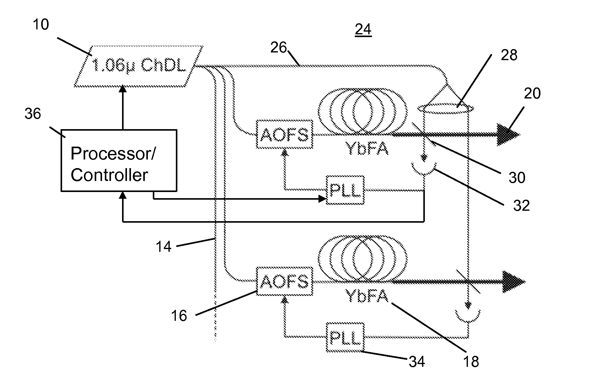
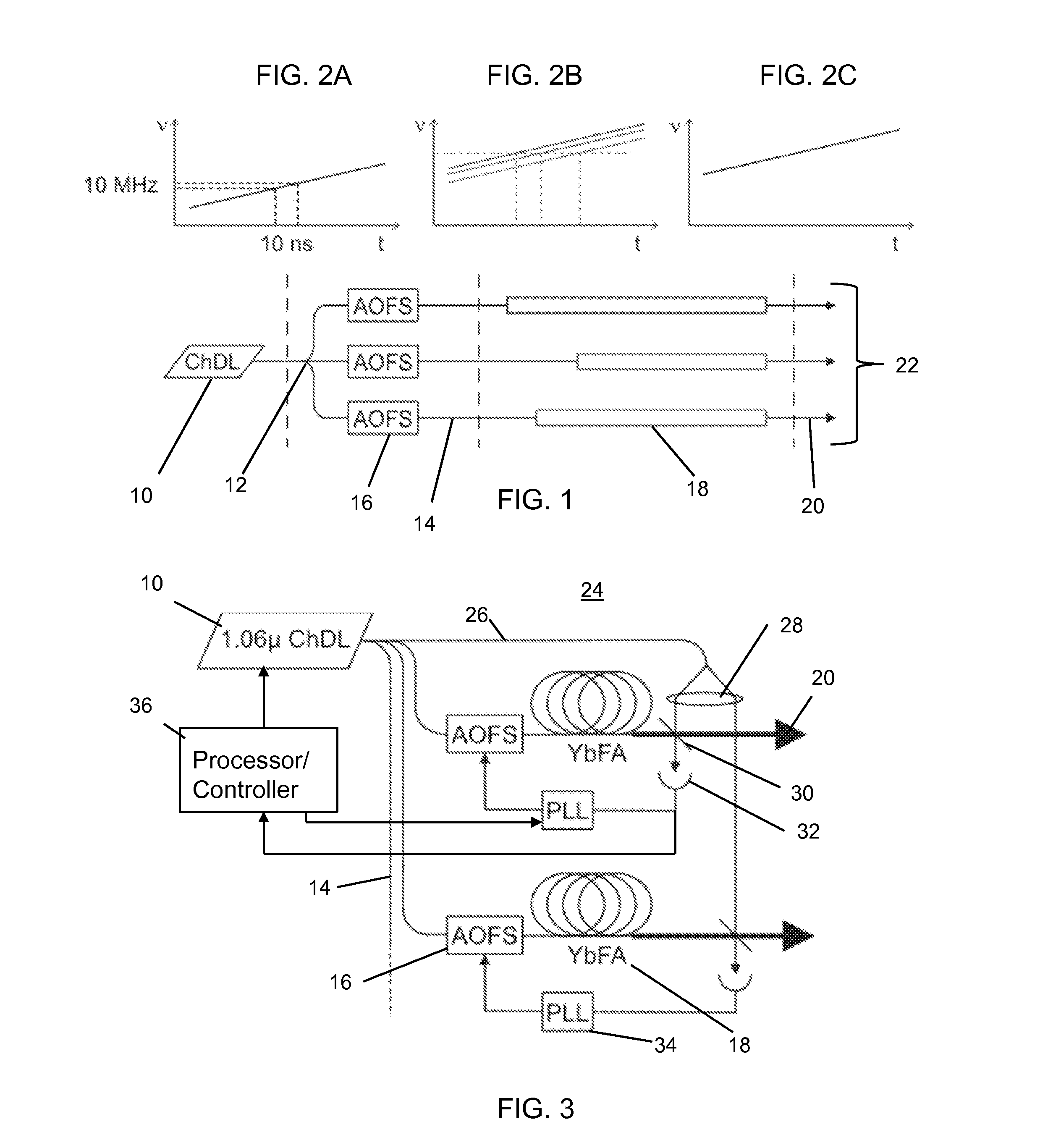
[0018]With reference to FIG. 1, the basic elements that are employed to implement the concepts of the present invention are illustrated. These elements include a highly-chirped diode laser (ChDL) 10 which has a chirp rate selected to be high enough to suppress the effects of SBS. In the preferred embodiment and as illustrated in the graph of FIG. 2A, a chirp rate of 10 MHz / 10 ns or 1015 Hz / s is employed. A chirp rate of at least 1014 Hz / s should be employed to insure suppression of the effects of SBS.

[0019]The frequency chirped output from the ChDL 10 is fed through a fiber splitter 12 to a plurality of parallel optical paths 14, each with a fiber-coupled acousto-optic frequency shifter (AOFS) 16 and a single-mode fiber amplifier 18. Each of the fiber amplifiers 18 has a path length that is dissimilar from one another as a result, for example, of normal variations in manufacturing tolerances. Without the use of the AOFS's 16, the dissimilar path lengths of the fiber amplifiers 18 wo...


PUM


Abstract

A chirped diode laser (ChDL) is employed for seeding optical amplifiers and / or dissimilar optical paths, which simultaneously suppresses stimulated Brillouin scattering (SBS) and enables coherent combination. The seed spectrum will appear broadband to suppress the SBS, but the well-defined chirp will have the coherence and duration to allow the active phasing of multiple amplifiers and / or dissimilar optical paths. The phasing is accomplished without optical path-length matching by interfering each amplifier output with a reference, processing the resulting signal with a phase lock loop, and using the error signal to drive an acousto-optic frequency shifter at the front end of each optical amplifier and / or optical path.

Description

CROSS REFERENCE TO RELATED APPLICATIONS[0001]This application claims the benefit under 35 USC 119(e) of U.S. Provisional Application No. 61 / 524,211, filed Aug. 16, 2011, which is hereby incorporated by reference in its entirety.BACKGROUND OF THE INVENTION[0002]1. Field of the Invention[0003]This invention relates to a semiconductor laser system, in particular, to an optical system comprised of a frequency-chirped semiconductor laser diode and dissimilar optical paths that are electronically phase-locked.[0004]2. Description of the Background Art[0005]Techniques to control the amplitude and phase of semiconductor laser diodes promise to extend the performance of laser diode systems and thereby enable a wide range of new applications. Presently, semiconductor lasers exhibit several favorable attributes, including low cost, small size and high electrical efficiency, which have made them key elements in communications systems and high power laser systems (e.g., for pumping fiber lasers)...

Claims


Application Information

Patent Timeline
IPC IPC(8): H01S3/10
CPCH01S3/06754H01S3/10015H01S2301/03H01S3/1618H01S3/2383H01S3/1307
Inventor RAKULJIC, GEORGE
Owner FUTUREWEI TECH INC
Learn More