Method and device for adjusting the mass flow rate of a gas stream

Active Publication Date: 2013-02-07
CENT NAT DE LA RECHERCHE SCI +1
View PDF30 Cites 9 Cited by
  • Summary
  • Abstract
  • Description
  • Claims
  • Application Information

AI Technical Summary

Benefits of technology

The invention proposes a method for controlling a stream that is easy and cost-effective to implement. The method allows for the production of pulsed jets at high frequencies. This technology advancement is useful for a variety of applications.

Problems solved by technology

However, these actuators do not make it possible to produce high speed micro-jets.
These actuators may produce micro-jets having a high outlet speed but cannot work at high frequency.
Furthermore, due to moving portions, the actuators of the prior art wear out quickly.
However, they do not make it possible to work at high frequency and great speed, which is required for wind tunnel tests and certain aeronautical and automobile applications.

Method used


Image

  • Method and device for adjusting the mass flow rate of a gas stream
  • Method and device for adjusting the mass flow rate of a gas stream

Examples


Embodiment Construction

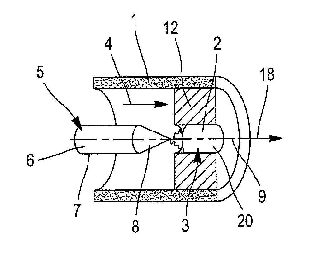
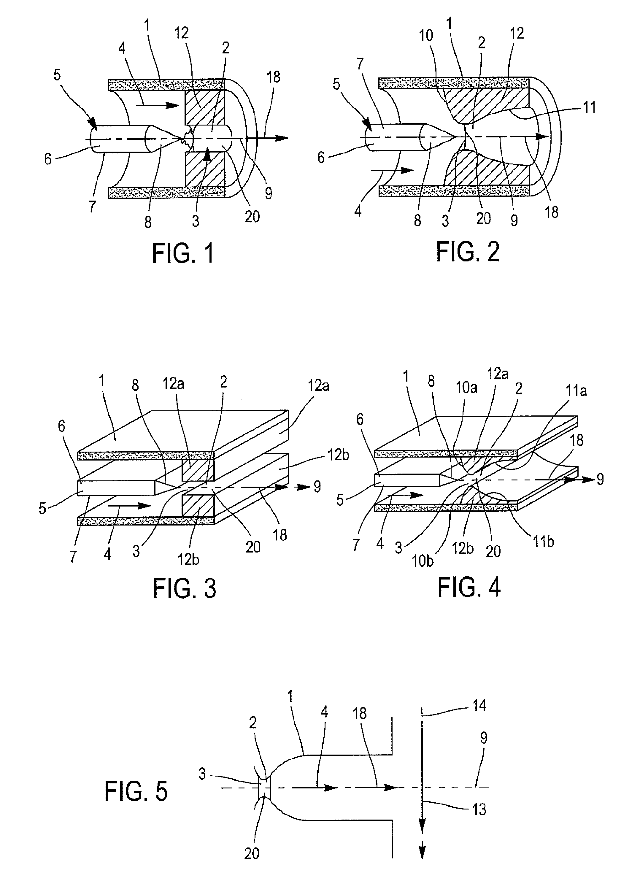
[0054]The device of FIG. 1 comprises a channel of cylindrical section. This channel 1 comprises a pipe 3. The pipe 3 is constituted by a narrowing 20 of the channel 1. This narrowing 20 is also called throat or sonic throat.

[0055]More precisely, the pipe 3 is formed by a cylindrical ring 12 with an inner diameter lower than the inner diameter of the channel 1 such that the pipe 3 constitutes a narrowing of the channel 1. The channel 1 and the pipe 3 are crossed by a gas stream 4 which flows in a flow direction 9. The gas stream 4 is permanent.

[0056]The gas stream 4 and the pipe 3 are selected such that the Mach number of the gas stream be equal to 1 in the pipe 3. In this example, the gas stream is an air flow. The device further comprises means for emitting an electrical discharge 5. The means 5 for emitting an electrical discharge are constituted here on the one hand of an electrode 6 placed in the centre of the channel 1 and aligned with the flow direction 9 and on the other hand...


PUM


Abstract

The invention relates to a method and device for controlling the mass flow rate of a sonic gas stream in a pipe. To carry out the above operation, an electric discharge is applied inside the pipe so as to create a plasma in the pipe. The electric discharge allows for an increase in the temperature of the gas stream and thus a variation in the mass flow rate or the pressure of the gas stream. By periodically emitting the electric discharge, a pulsed or adjustable gas jet is obtained at the outlet of the device. The gas jet can then be used to control a main stream.

Description

TECHNICAL FIELD OF THE INVENTION[0001]The invention relates to a method and a device for adjusting the mass flow rate of a gas stream.PRIOR ART[0002]In the aeronautics field, it has been known to use gas jets for controlling a stream. Thus, documents US2002 / 0195526 or EP1623922 describe the use of pulsed actuators emitting gas micro-jets to control streams. These gas micro-jets particularly make it possible to control the shape, direction, section and even the envelope of the streams.[0003]For this, different types of actuators are known. For example, there has been known actuators with synthetic jets such as described in document US2002 / 0195526. However, these actuators do not make it possible to produce high speed micro-jets.[0004]There has also been known of actuators which operate using valves. These actuators may produce micro-jets having a high outlet speed but cannot work at high frequency.[0005]Furthermore, due to moving portions, the actuators of the prior art wear out quic...

Claims


Application Information

Patent Timeline
IPC IPC(8): F17D3/00
CPCB64C23/005F15D1/12B64C2230/18H05H1/24Y02T50/166G05D7/0629Y10T137/0324Y10T137/8593Y02T50/10H05H1/245H05H1/3484H05H1/48H05H2245/15
Inventor BONNET, JEAN-PAULLEBEDEV, ANTONMOREAU, ERICBENARD, NICOLAS
Owner CENT NAT DE LA RECHERCHE SCI
Why Eureka
Try Eureka