
Self-Testing Combustible Gas and Hydrogen Sulfide Detection Apparatus

a detection apparatus and combustible gas technology, applied in the direction of measurement devices, scientific instruments, instruments, etc., can solve the problems of time-consuming, putting the employee performing the calibration at risk for operational hazards, and the sensor used in the fixed detector can become disabled or “poisoned” and other problems, to achieve the effect of simple, convenient and reliabl

Active Publication Date: 2013-02-07
SAUDI ARABIAN OIL CO
View PDF28 Cites 8 Cited by
  • Summary
  • Abstract
  • Description
  • Claims
  • Application Information

AI Technical Summary

Benefits of technology

The present invention is a sensor calibration system that includes a burst valve assembly for delivering testing material to a sensor without causing damage or desensitization. The system includes a sensor diffuser for promoting a uniform distribution of the testing material to the sensor. The burst valve assembly can be connected to a supplemental storage container to reduce pressure on the burst valve assembly during use. The system allows for more frequent calibration at a lower cost compared to manual calibration and also reduces the need for mobile calibration equipment. The system includes a pressure monitoring system for monitoring the pressure of the storage container and alerting operations when additional testing material is needed. The detector can be placed in a different location without replacing the storage container. Overall, the invention provides a simple, convenient and reliable method for calibrating sensors in the field.

Problems solved by technology

However, the sensors used within the fixed detectors can become disabled or “poisoned” over time.
The process is performed manually at the site of the sensor, which is typically a site of increased risk for exposure to hazardous gaseous emissions, thereby necessitating the placement of the sensor to monitor conditions.
As such, the standard method is time consuming and puts the employee performing the calibrations at risk for operational hazards.
Similarly, weathering can degrade the ability to review manual markings of testing dates.

Method used


Image

  • Self-Testing Combustible Gas and Hydrogen Sulfide Detection Apparatus
  • Self-Testing Combustible Gas and Hydrogen Sulfide Detection Apparatus
  • Self-Testing Combustible Gas and Hydrogen Sulfide Detection Apparatus

Examples


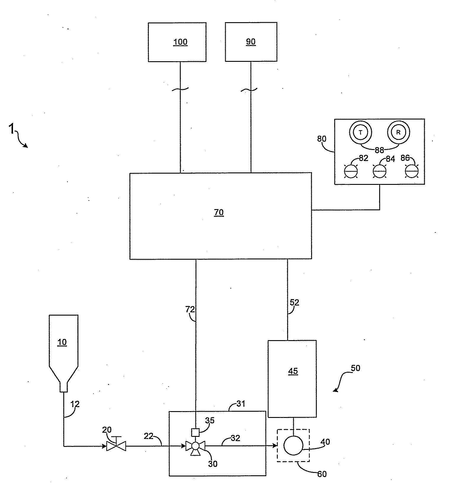
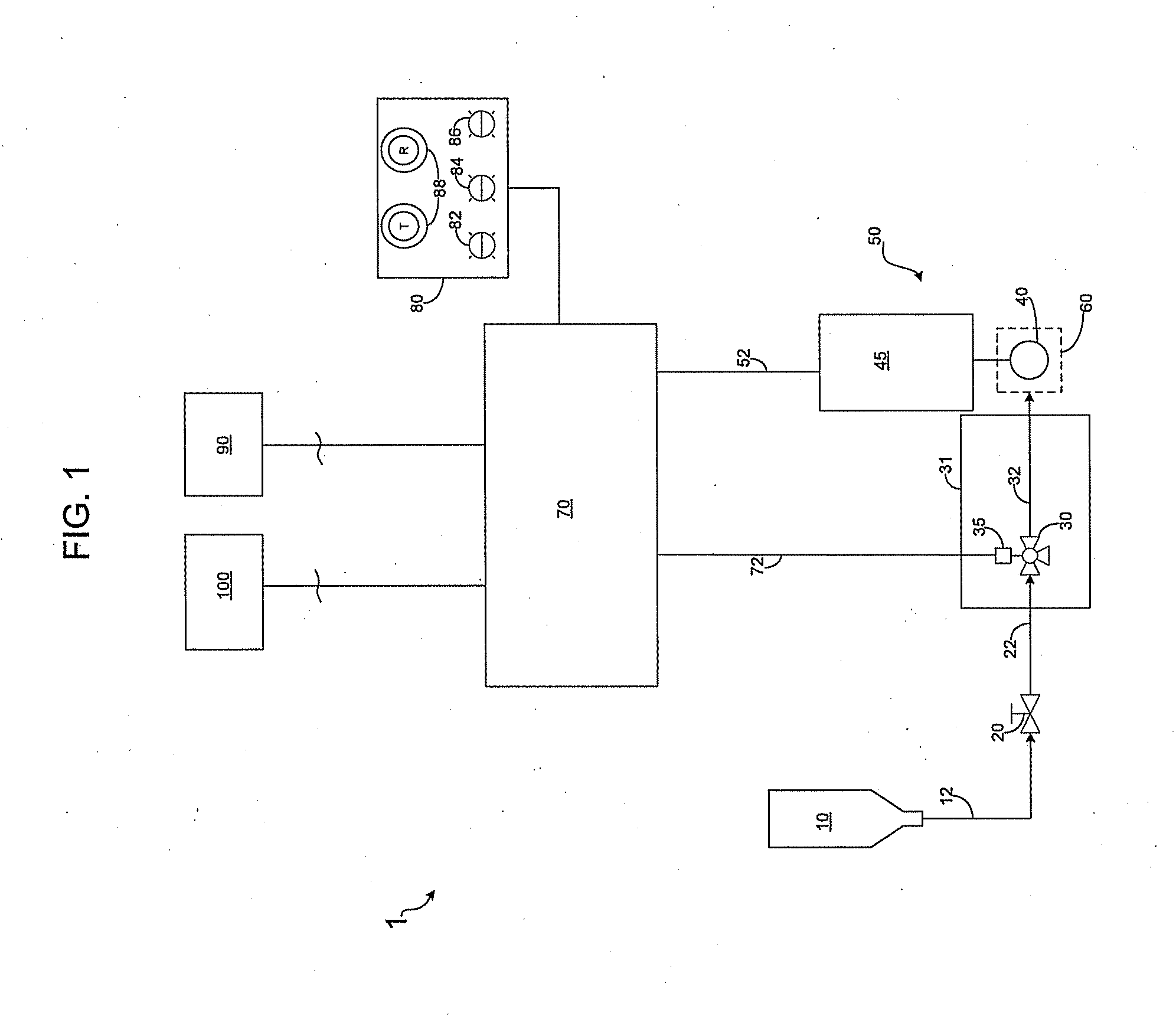
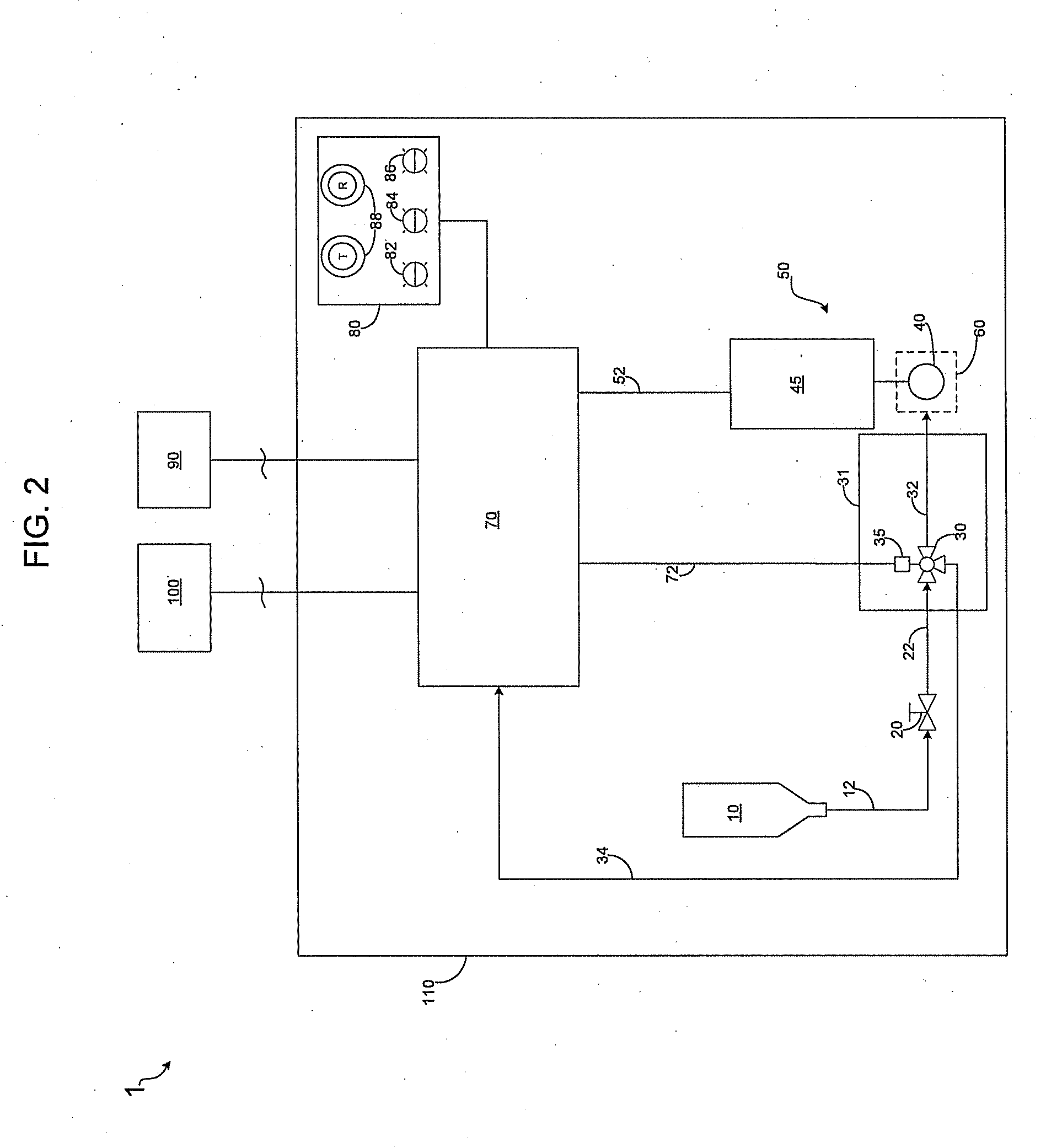
Embodiment Construction

[0032]While the invention will be described in connection with several embodiments, it will be understood that it is not intended to limit the invention to those embodiments. On the contrary, it is intended to cover all the alternatives, modifications and equivalence as may be included within the spirit and scope of the invention defined by the appended claims.

[0033]In one embodiment, the automated testing apparatus for detecting the chemical substance is in a fixed location and can include the sensor, the storage container, the burst valve assembly in fluid communication with the storage container, and the testing control module in communication with the burst valve assembly. The automated testing apparatus acts to notify operations of sensor failures or calibration issues in a timely fashion, and without the need for a manual check of the sensor locally. In an additional embodiment, the automated testing apparatus is operable to test the ability of fixed gas detectors to properly ...


PUM


Abstract

An automated testing apparatus for remotely performing a testing sequence to ensure that a sensor is functioning. The apparatus can include a detector, a storage container, a burst valve in fluid communication with the storage container, a testing control module in communication with the storage container and the burst valve, and a remote user interface remotely located from the detector. Preferably, the automated testing apparatus can simplify the testing procedure, increase the frequency of sensor testings, thereby notifying operations of sensor failures in a more timely fashion without the need for an operator to check the sensor locally.

Description

TECHNICAL FIELD OF THE INVENTION[0001]The present invention relates to a method and apparatus for safely ensuring the functionality of combustible gas and hydrogen sulfide detectors.BACKGROUND OF THE INVENTION[0002]Within many operating facilities and well sites, fixed gas detection systems are deployed to warn employees of a dangerous release of hydrogen sulfide or combustible gases. However, the sensors used within the fixed detectors can become disabled or “poisoned” over time. In this state, although the sensor has lost sensitivity to the targeted gas, the detector appears to otherwise operate normally. To test for this failure of sensitivity, field level calibrations are conducted on a regular basis.[0003]Within operations, a full calibration test interval is generally prescribed at a minimum of 90 days, with an interval of 30 days for some higher risk applications. Conventional methods require the external application of target gas using a jar with glass ampoules or with a por...

Claims


Application Information

Patent Timeline
IPC IPC(8): G01M15/10
CPCG01N33/0006G01N33/007G01N33/0044G01N33/004
Inventor FLANDERS, PATRICK S.
Owner SAUDI ARABIAN OIL CO
Learn More