Device for Providing Hot Exhaust Gases

a technology of hot exhaust gas and turbine, which is applied in the direction of machines/engines, electrochemical generators, lighting and heating apparatus, etc., can solve the problems of generating a certain degree of residual heat in the exhaust gas, affecting the efficiency of the heat exchanger, etc., to achieve high controllability and reliable ignition of the fuel, and the effect of safe and reliable starting

Inactive Publication Date: 2013-01-31
DAIMLER AG
View PDF5 Cites 0 Cited by
  • Summary
  • Abstract
  • Description
  • Claims
  • Application Information

AI Technical Summary

Benefits of technology

[0009]In a very advantageous and expedient further development of the device according to the invention, the burner can be intermittently supplied with fresh air, the burner comprising an ignition device by which a combustion of at least the fresh air and the fuel of the fuel cell can be initiated. The burner is therefore supplied, in addition to the exhaust gas of the fuel cell and the at least intermittent supply of fuel, with fresh air. This fresh air, which is preferably supplied together with the fuel, then makes it possible to initiate a combustion of the air and the fuel via an ignition device installed into the burner. Due to this ignition, which for example happens upstream of the combustion zone proper in the direction of flow, e.g. upstream of the porous structure of a pore burner, the burner can always be started safely and reliably by means of the upstream ignition device. This ensures that the desired hot exhaust gases, which can for example be used for driving a turbine, are always available when required. Furthermore, the fuel and the exhaust gas from the fuel cell can always be fully converted in the region of the burner, so that there is no emission of hydrogen, hydrocarbons, carbon monoxide, nitrogen oxides (NOx) or the like into the environment of the fuel cell.
[0010]In a very advantageous and expedient further development, fresh air and fuel can be merged with the exhaust gases from the fuel cell downstream of the ignition device and upstream of the combustion zone in the direction of flow. This design allows for a highly controllable and reliable ignition of the fuel together with the added fresh air, while the exhaust gases are only merged with this already burning mixture after ignition, before or when the combustion zone is reached. This offers the advantage that, irrespective of the composition of the exhaust gases, an ignitable mixture can always be obtained, because in the region of the ignition device only the fuel and the fresh air are present, the mixing ratio of which can be controlled easily without having to determine, for example, the residual fuel content and the residual oxygen content of the exhaust gases using expensive and complex sensor systems.

Problems solved by technology

This design has the disadvantage that such a burner, owing to the very high temperatures and the difficulties involved in controlling combustion, causes the emission of a lot of undesirable materials, for example NOx emissions.
This causes the generation of a certain degree of residual heat in the exhaust gas, which has to be recovered by means of a heat exchanger in a comparably complex and expensive manner.
In addition, the assembly, which is compact with regard to the burner, becomes larger by adding the catalytic converter.
Although these designs are capable of providing hot gases in the fuel cell system, there is frequently no guarantee that all of the undesirable residues present in the exhaust gas of the fuel cell, such as hydrocarbons when using a gas generation system as described in the JP abstract or hydrogen residue when using a hydrogen reservoir as described in the DE specification, are completely converted.
This is typically due to the fact that a secure and reliable initiation of the catalytic reaction in the burner can often only be achieved with major difficulties and is not sufficiently repeatable.

Method used


Image

  • Device for Providing Hot Exhaust Gases
  • Device for Providing Hot Exhaust Gases
  • Device for Providing Hot Exhaust Gases

Examples


Embodiment Construction

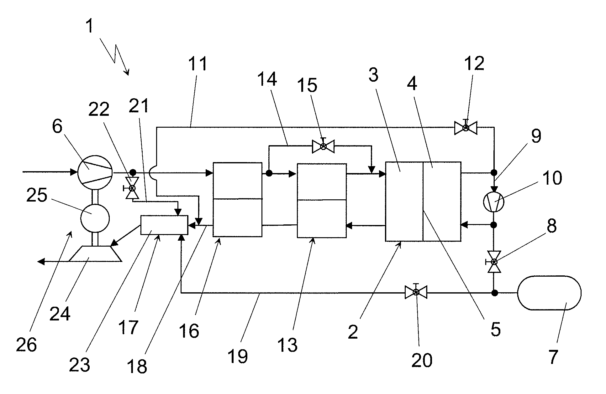
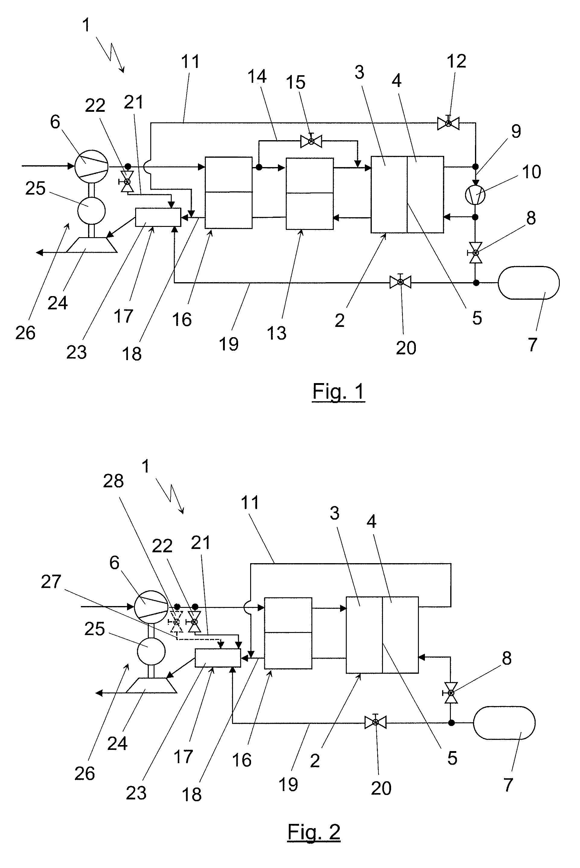
[0022]FIGS. 1 and 2 show two different designs of fuel cell systems 1, which are the preferred, but not the sole, application for the device according to the invention for the provision of hot exhaust gases. The core of the fuel cell system 1 is a fuel cell 2, which may for example be a stack of PEM fuel cells. A cathode compartment 3 and an anode compartment 4 of the fuel cell 2 are separated from each other by proton-conducting membranes 5. The oxidant for the operation of the fuel cell 2 is typically the oxygen in the air, air being piped into the cathode compartment 3 via an air conveying device 6. The anode compartment 4 is supplied with hydrogen or with a gas containing hydrogen. In the illustrated embodiment, hydrogen is to be supplied to the anode compartment 4 of the fuel cell 2 from a compressed gas reservoir 7. The hydrogen stored under high pressure in this compressed gas reservoir 7 is fed into the anode compartment 4 via a valve device 8 and in this process expanded to...


PUM

PropertyMeasurementUnit
temperatureaaaaaaaaaa
specific surface areaaaaaaaaaaa
electric energyaaaaaaaaaa

Abstract

A device used to provide hot exhaust gases for driving a turbine. The device includes a burner, the combustion zone of which is directly mounted on or integrated into the gas inlet (turbine housing) of the turbine. The burner is supplied with at least one combustible gas or gas mixture. The combustion zone includes a porous material with a large specific surface area.

Description

BACKGROUND AND SUMMARY OF THE INVENTION[0001]Exemplary embodiments of the present invention relate to a device for the provision of hot exhaust gases for driving a turbine and to the use of a device of this type.[0002]The principle of operating turbines with hot exhaust gases from a combustion process is known. U.S. Patent Application Publication No. 2002 / 0157881 A1, for example, describes an assembly in which electric energy is provided for a vehicle by means of a turbine driven via a burner and by means of a generator. The special feature of this arrangement is that the burner is integrated into the turbine or the turbine intake housing. The burner itself is designed as a flame burner that provides as high a temperature as possible for the operation of the turbine. This design has the disadvantage that such a burner, owing to the very high temperatures and the difficulties involved in controlling combustion, causes the emission of a lot of undesirable materials, for example NOx em...

Claims


Application Information

Patent Timeline
Patent Type & Authority Applications(United States)
IPC IPC(8): F23R3/40H01M8/06F02C7/266
CPCF23R3/40F23C99/006
Inventor STARK, HOLGERMEX, ULF-MICHAELKONRAD, GERHARDSTEINHAUSER, BENJAMINHINSENKAMP, GERT
Owner DAIMLER AG
Why Eureka
Try Eureka