Eureka AIR delivers breakthrough ideas for toughest innovation challenges, trusted by R&D personnel around the world.

Distributed optical fiber sensor based on roman and brillouin scattering

a technology of optical fiber and scattering, applied in the field of optical fiber sensing, can solve the problems of high cost, low measurement accuracy of temperature or strain, high cost of optical fiber raman amplifier, etc., and achieve the effect of enhancing the signal-to-noise ratio of the system

Inactive Publication Date: 2013-01-24
CHINA JILIANG UNIV
View PDF6 Cites 45 Cited by
  • Summary
  • Abstract
  • Description
  • Claims
  • Application Information

AI Technical Summary

Benefits of technology

The patent describes a new sensor system that can measure temperature and strain in optical fibers simultaneously using two laser light sources. These sources have different wavelengths, which are measured through a technique called wavelength division multiplexing. This simultaneous measurement increases the signal-to-noise ratio of the system and improves the accuracy of the measurements. The sensor system uses a fusion of two theories, making it more robust and precise.

Problems solved by technology

However, the optical fiber Raman amplifier is expensive and high in cost.
However, as the optical fiber Brillouin scattering has narrow spectrum bandwidth, the measurement precision of temperatures or strains is low (M. N. Allahbabi, Y. T. Cho and T. P. Newson, Simulataneous Distributed Measurements of Temperature and Strain using Spontaneous Raman and Brillouin Scattering, Optics Letters, 2005, 1 Jun., p.
However, an optical fiber Raman amplifier is embedded into the system, which tends to cause mutual interference due to non-linear effect of the optical fiber.
Moreover, the optical fiber Raman amplifier is expensive and high in cost.

Method used


Image

  • Distributed optical fiber sensor based on roman and brillouin scattering
  • Distributed optical fiber sensor based on roman and brillouin scattering
  • Distributed optical fiber sensor based on roman and brillouin scattering

Examples


Embodiment Construction

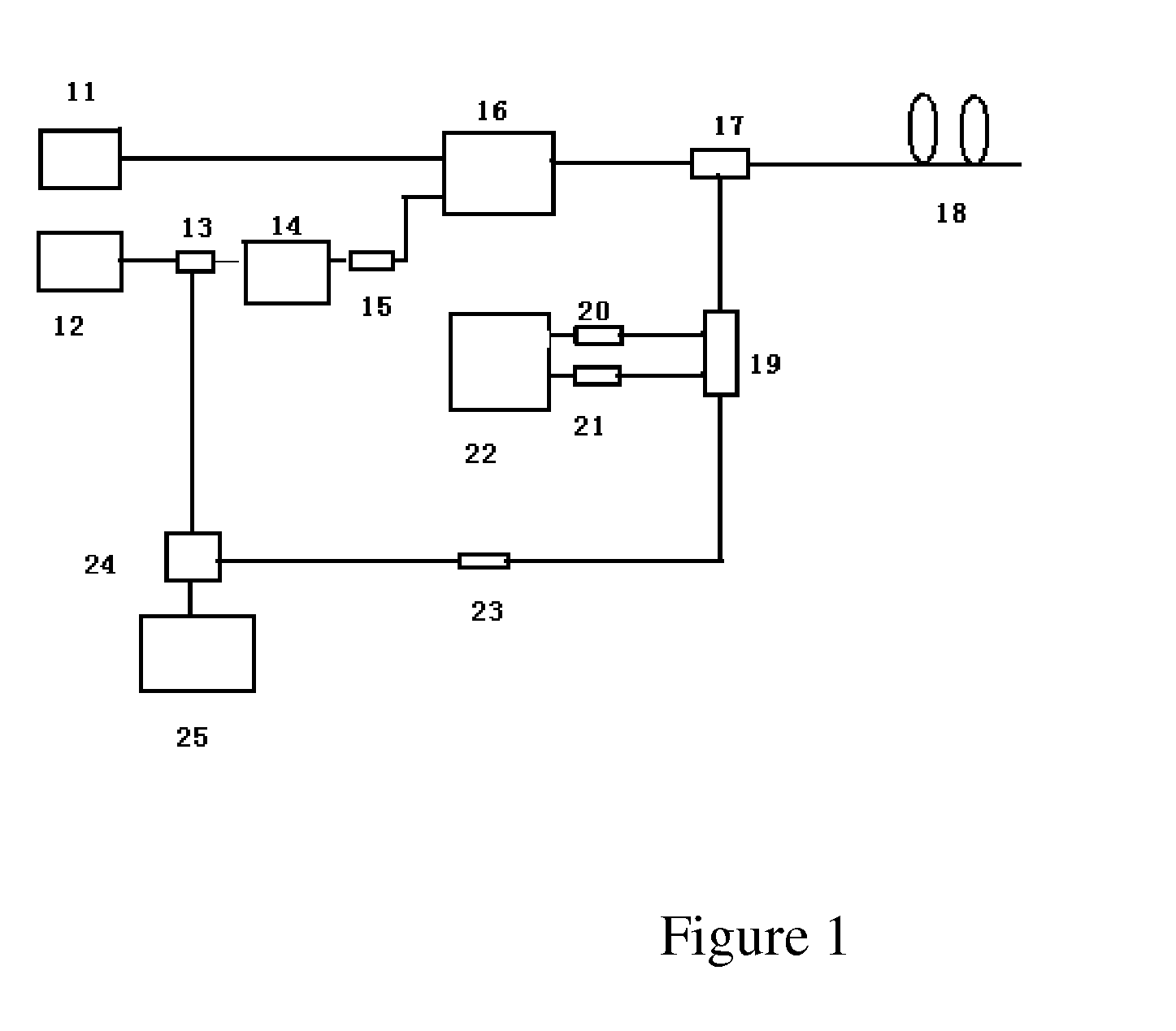
[0020]Referring to FIG. 1, the distributed optical fiber sensor based on Raman and Brillouin scattering in the present invention includes: a semiconductor FP cavity pulsed wideband optical fiber laser 11, a semiconductor external-cavity continuous narrowband optical fiber laser 12, a wave separator 13, an electro-optic modulator 14, an isolator 15, an Er-doped optical fiber amplifier 16, a bidirectional coupler 17, an integrated wavelength division multiplexer 19, a first photoelectric receiving and amplifying module 20, a second photoelectric receiving and amplifying module 21, a direct detection system 22, a narrowband optical fiber transmission grating 23, a circulator 24, and a coherence detection module 25.

[0021]In an embodiment, an output terminal of the semiconductor FP cavity pulsed wideband optical fiber laser 11 is connected with an input terminal of the Er-doped optical fiber amplifier 16; an output terminal of the semiconductor external-cavity continuous narrowband optic...


PUM


Abstract

A distributed optical fiber sensor based on Raman and Brillouin scattering is provided. The distributed optical fiber sensor includes a semiconductor FP cavity pulsed wideband optical fiber laser (11), a semiconductor external-cavity continuous narrowband optical fiber laser (12), a wave separator (13), an electro-optic modulator (14), an isolator (15), an Er-doped optical fiber amplifier (16), a bidirectional coupler (17), an integrated wavelength division multiplexer (19), a first photoelectric receiving and amplifying module (20), a second photoelectric receiving and amplifying module (21), a direct detection system (22), a narrowband optical fiber transmission grating (23), a circulator (24) and a coherence detection module (25). The temperature and the strain can be measured simultaneously, and the signal-to-noise ratio of the system is enhanced.

Description

TECHNICAL FIELD[0001]The present invention relates to a technical field of optical fiber sensing, and specifically to a distributed optical fiber sensor based on Raman and Brillouin scattering.BACKGROUND OF THE INVENTION[0002]In the field of distributed optical fiber sensors, there are distributed optical fiber Raman scattering photon temperature sensors and distributed Brillouin scattering photon sensors. In the Chinese patent CN101324424, the detection and pumping light source is adopted, an optical fiber Raman amplifier is used to replace a traditional optical fiber Brillouin amplifier to obtain backward optical fiber Stimulated Brillouin Scattering (SBS) light ray, and strain information is obtained by measurement of the frequency shifts of the SBS light ray. However, the optical fiber Raman amplifier is expensive and high in cost. Using a narrowband laser light source, the Newson research team from University of Southampton in United Kingdom measures fiber temperature variation...

Claims


Application Information

Patent Timeline
IPC IPC(8): G01N21/65G01K11/3206G01K11/322G01K11/324
CPCG01B11/16G01D5/35364G01L1/247G01L1/242G01K11/32
Inventor ZHANG, ZAIXUANLI, CHENXIAJIN, SHANGZHONGWANG, JIANFENGGONG, HUAPINGLI, YI
Owner CHINA JILIANG UNIV
Why Eureka
Eureka Blog
Learn More