Yoke for a Cross Type Universal Joint and Manufacturing Method Thereof
a cross-type universal joint and manufacturing method technology, applied in the direction of manufacturing tools, couplings, mechanical devices, etc., can solve the problems of reducing the durability of the bolt, reducing the service life of the bolt, so as to reduce the bending or breakage of the bolt, prevent large forces in the bending direction of the bolt, and reduce the cost
- Summary
- Abstract
- Description
- Claims
- Application Information
AI Technical Summary
Benefits of technology
Problems solved by technology
Method used
Image


Examples
example 1
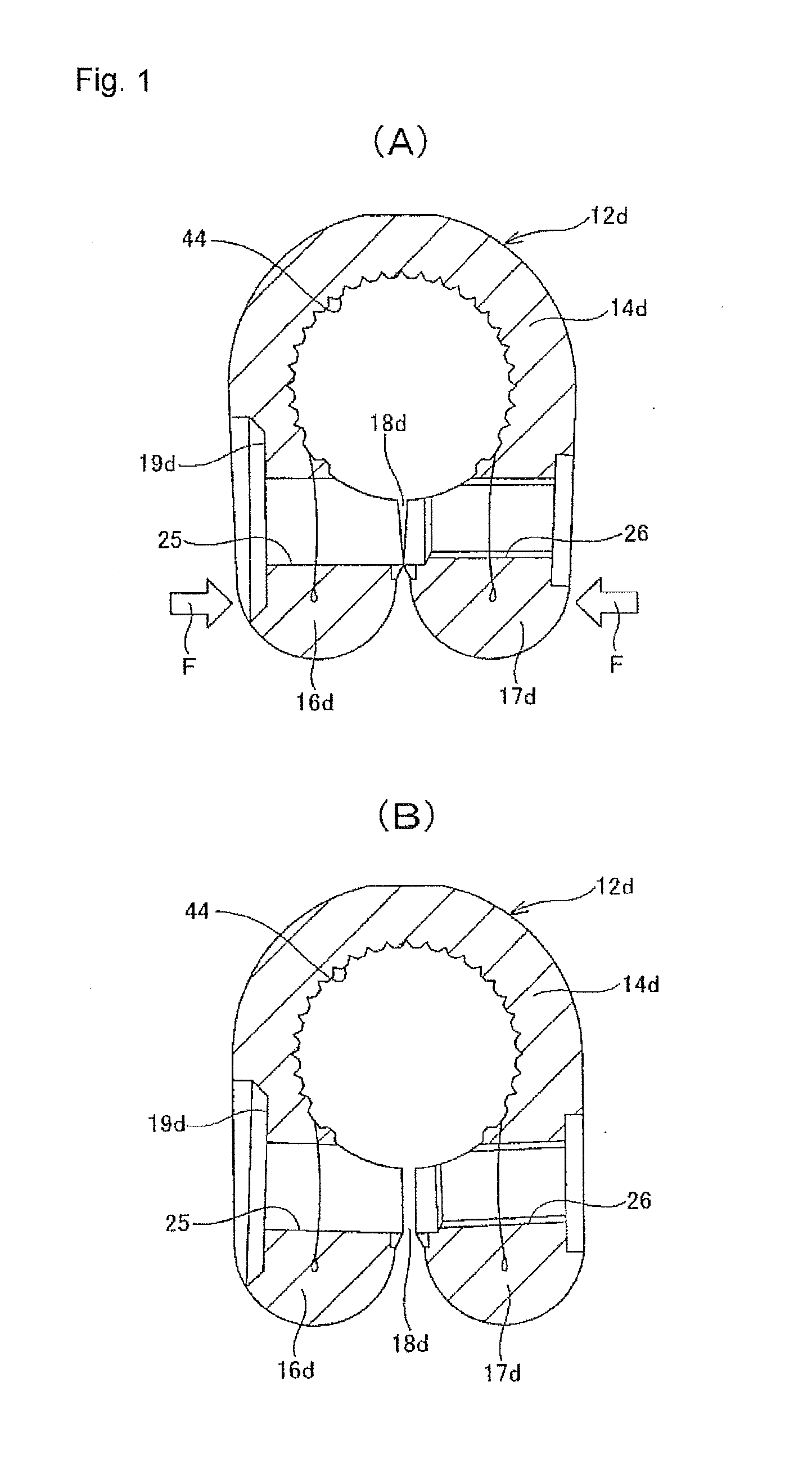
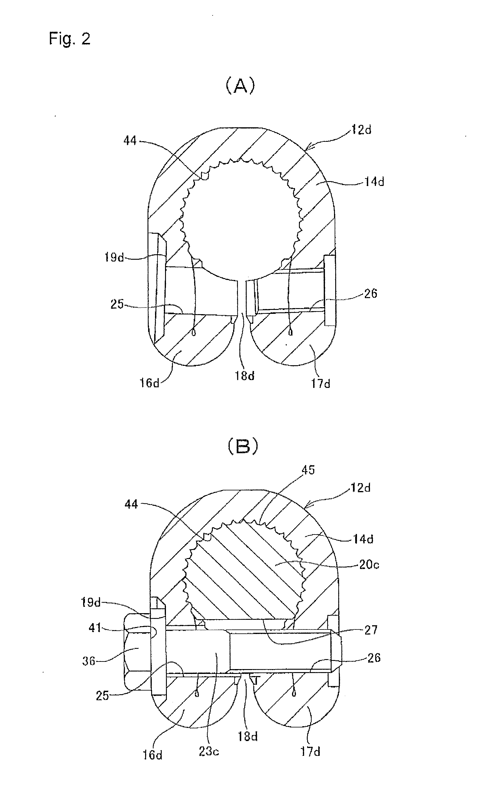
[0066]FIGS. 1(A) to 2(B) illustrate a first example of the present invention. Common features of the present invention, including this example, are construction making it possible to ease the force in the bending direction that is applied to the bolt 23c even though there is elastic deformation of the first flange section 16d and second flange section 17d that occurs as the bolt 23c is tightened, and also the manufacturing method for obtaining such construction.
[0067]More specifically, in regards to the construction of the yoke 12d, with the bolt 23c inserted through the through hole 25, screwed into the screw hole 26 and further tightened, the inside surface of the head section of this bolt 23 and the seating surface section 19d are kept parallel.
[0068]Moreover, in regards to the method of manufacturing the yoke 12d, the process of forming the through hole 25, screw hole 26 and seating surface section 19d in the first flange section 16d and second flange section 17d is devised such...
example 2
[0077]FIGS. 3(A) and 3(B) illustrate a second example of the present invention. In this example, in the manufacturing process illustrated in FIGS. 12(A) to 12(E), in the stage of the fourth intermediate member 35 illustrated in FIG. 12(E), the inner diameter of the base section (pitch circle diameter of the female serrations 44) is nearly the same as the outer diameter of the end section of the rotating shaft 20c (pitch circle diameter of the male serrations 45). Also, in this state, the through hole 25, screw hole 26 and seating surface section 19d are formed in the first and second flange sections 16d, 17d. In this example as well, the through hole 25 and screw hole 26 are concentrically processed, and the seating surface section 19d is formed in a direction that is orthogonal to the center axis of the holes 25, 26, so the work of processing the seating surface section 19d and holes 25, 26 can be performed easily and with good precision.
[0078]After the through hole 25, screw hole ...
example 3
[0080]FIG. 4 illustrates a third example of the present invention. In this example, with a support shaft 43 having the same shape and dimensions as the end section of the rotating shaft 20 fitted inside the base section 14d in the place of the rotating shaft 20c that is to be joined and fastened to the base section 14d of the yoke 12d, a force F is applied to both the first and second flange sections 16d, 17d in directions toward each other, and the inner diameter of the base section 14d is elastically reduced. In doing so, with the inner diameter of the base section 14d reduced, the through hole 25, screw hole 26 and seating surface section 19d are formed in the first and second flange sections 16d, 17d.
[0081]In the case of this example, when forming the through hole 25, screw hole 26 and seating surface section 19d, the formation state of the base section 14d is closer to the actual state of use of the yoke 12d. Therefore, bending of the bolt 23c during use can be even further re...
PUM
| Property | Measurement | Unit |
|---|---|---|
| pitch circle diameter | aaaaa | aaaaa |
| length | aaaaa | aaaaa |
| width | aaaaa | aaaaa |
Abstract
Description
Claims
Application Information
 - R&D
- Intellectual Property
- Life Sciences
- Materials
- Tech Scout
- Unparalleled Data Quality
- Higher Quality Content
- 60% Fewer Hallucinations
Browse by: Latest US Patents, China's latest patents, Technical Efficacy Thesaurus, Application Domain, Technology Topic, Popular Technical Reports.
© 2025 PatSnap. All rights reserved.Legal|Privacy policy|Modern Slavery Act Transparency Statement|Sitemap|About US| Contact US: help@patsnap.com