
Pneumatic tire with specified bead core and method for manufacturing the same

a pneumatic tire and bead core technology, applied in the field of pneumatic tires, can solve the problems that the risk of the degradation of the durability of the carcass ply cannot be sufficiently avoided, and achieve the effects of reducing the stress concentration at the carcass ply, preventing the risk of the degradation of the durability of the carcass, and reducing the stress concentration

Active Publication Date: 2017-10-03
BRIDGESTONE CORP
View PDF10 Cites 4 Cited by
  • Summary
  • Abstract
  • Description
  • Claims
  • Application Information

AI Technical Summary

Benefits of technology

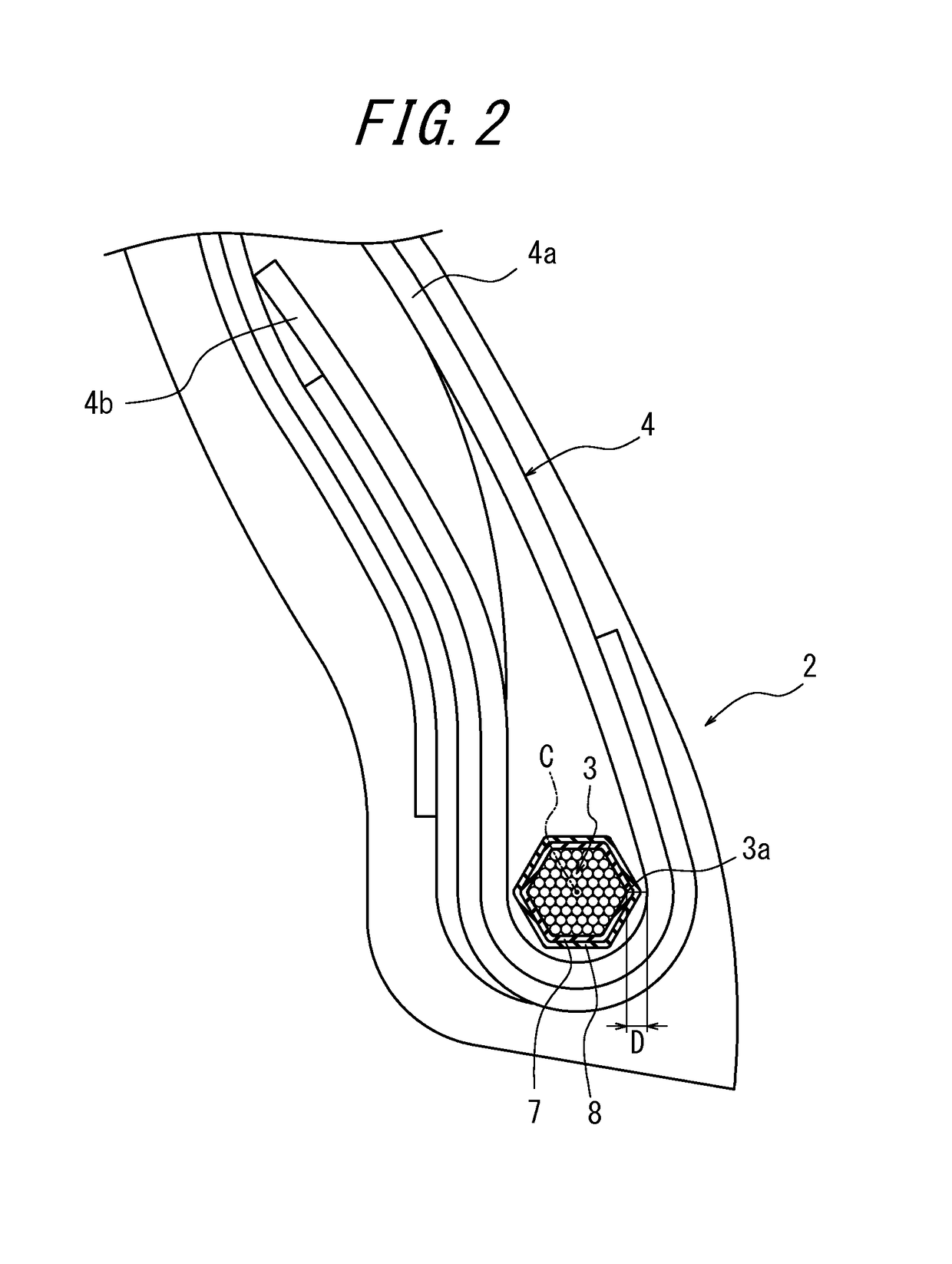
The present invention relates to a pneumatic tire with improved durability. The tire has two or more reinforcement layers with organic fiber over a bead core, which reduces stress concentration at the carcass ply and prevents degradation of durability. The inner reinforcement layer with organic fiber has its rubber-coated organic fiber cord coiled without overlapping, preventing localized force application. The outer reinforcement layer with organic fiber secures the rubber layer over the entire circumferential surface of the bead core, preventing thermal degradation. When the distance between the body of the carcass ply and the corner of the bead core is between 2 millimeters and 3 millimeters, the stress concentration is reduced and holding force on the carcass ply is maintained, without excessive rubber degradation. When the ratio of the length of the bead core in a tire radial direction to the length of the bead core in the tire width direction is between 1:0.8 and 1:1.2, the stress concentration at the carcass ply pressed by the corner is further reduced, preventing degradation of durability.

Problems solved by technology

As a result, risk of the degradation of durability of the carcass ply still cannot be sufficiently avoided.

Method used


Image

  • Pneumatic tire with specified bead core and method for manufacturing the same
  • Pneumatic tire with specified bead core and method for manufacturing the same
  • Pneumatic tire with specified bead core and method for manufacturing the same

Examples


examples

[0069]Pneumatic tires according to the present invention were prototyped to evaluate performance as follows.

[0070]Example Tires of size 11.00R20 and 12.00R20, and Conventional Tires of size 11.00R20 and 12.00R20 were produced.

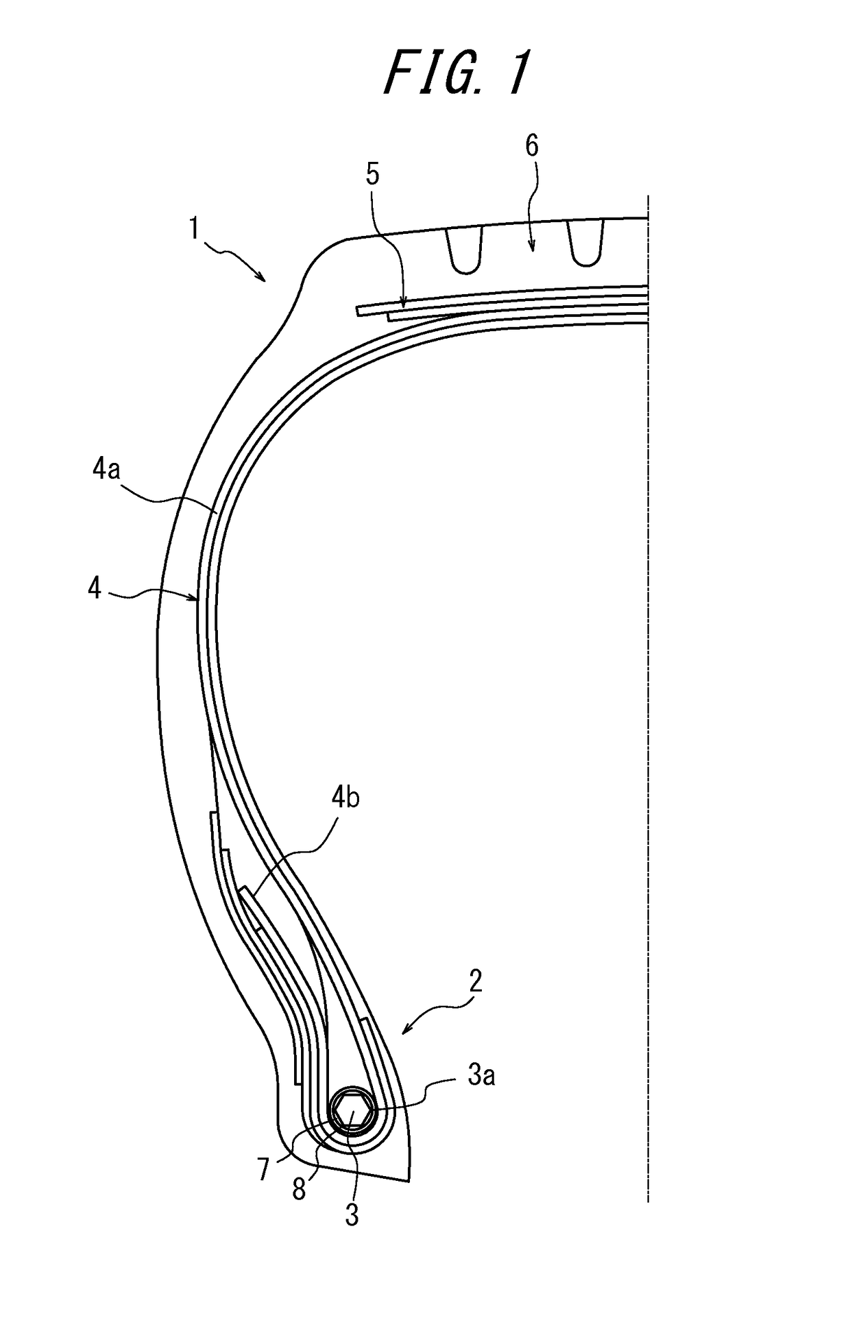
[0071]Example Tire 1 of size 12.00R20 had a similar feature to a tire 1 illustrated in FIGS. 1 and 2. Two reinforcement layers with organic fiber were formed over a bead core of the tire. The organic fiber cord of the reinforcement layer with organic fiber was made of nylon. An intersecting angle between a cord in the inner reinforcement layer and a cord in the outer reinforcement layer was 100 degrees.

[0072]As illustrated in FIG. 6(a), the bead core of the Example Tire 1 was formed by repeatedly coiling a cord to form nine columns. Numbers of rows in each column from the innermost column to the outermost column in a tire radial direction were increased and decreased and were 6, 7, 8, 9, 10, 9, 8, 7 and 6, respectively. The ratio of length of the bead core in a...


PUM

PropertyMeasurementUnit
distanceaaaaaaaaaa
elevation angleaaaaaaaaaa

Abstract

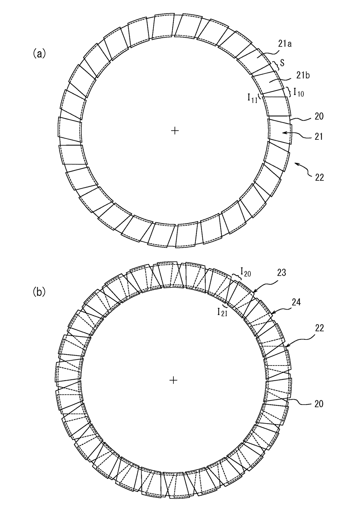
Provided is a pneumatic tire having laminated reinforcement layers with organic fiber over a polygonal cross-section bead core, and in the layer, a rubber-coated organic fiber cord is tilted to the center line of the bead core in a transverse section and is spirally coiled, in which each organic fiber cord in an inner and outer adjacent reinforcement layers over the bead core extends such that an organic fiber cord in the inner reinforcement layer and an organic fiber cord in the outer reinforcement layer intersect each other relative to the center line of the bead core in the transverse section, in which in the inner reinforcement layer, the cord is coiled with space at least partially in a tire circumferential direction such that the cord does not overlap in the tire circumferential direction, and the outer reinforcement layer is arranged to cover at least a part of the space.

Description

[0001]This is a National Stage of Application No. PCTJP2012 / 004689 filed Jul. 24, 2012, claiming priority based on Japanese Patent Application No. 2011-164722 filed Jul. 27, 2011.TECHNICAL FIELD[0002]The present invention relates to a pneumatic tire including: a pair of annular bead cores embedded and arranged in bead portions; a carcass formed of at least one carcass ply including a body and a folded portion connected to the body, the body toroidally extending between the pair of the bead cores, the folded portion folded around the bead core; and a tread rubber arranged on outer side of the periphery of a crown region of the carcass, in a cross section in a tire width direction, the bead core having a polygonal shape and the polygonal shape having at least one corner on the side of the body of the carcass ply. In particular, the present invention relates to a pneumatic tire preferably used as a heavy load tire for trucks or buses. The present invention also relates to a method for ...

Claims


Application Information

Patent Timeline
Patent Type & Authority Patents(United States)
IPC IPC(8): B60C15/04B29D30/50
CPCB60C15/04B29D30/50B60C2015/044Y10T152/10819
Inventor MITA, KEIICHI
Owner BRIDGESTONE CORP
Learn More