
Screw terminal block and attachment plug including the same

a technology of screw terminal block and screw terminal plug, which is applied in the direction of clamped/spring connection, electrical equipment, connections, etc., can solve the problem of difficult rotation of washer in conjunction with the terminal screw

Active Publication Date: 2013-01-17
PANASONIC CORP
View PDF5 Cites 17 Cited by
  • Summary
  • Abstract
  • Description
  • Claims
  • Application Information

AI Technical Summary

Benefits of technology

The present invention introduces a screw terminal block and an attachment plug that can prevent the terminal screw from becoming loose.

Problems solved by technology

The washer comes into contact with a wall provided in the terminal base made of a resin, which makes it difficult to rotate the washer in conjunction with the terminal screw.

Method used


Image

  • Screw terminal block and attachment plug including the same
  • Screw terminal block and attachment plug including the same
  • Screw terminal block and attachment plug including the same

Examples


first embodiment

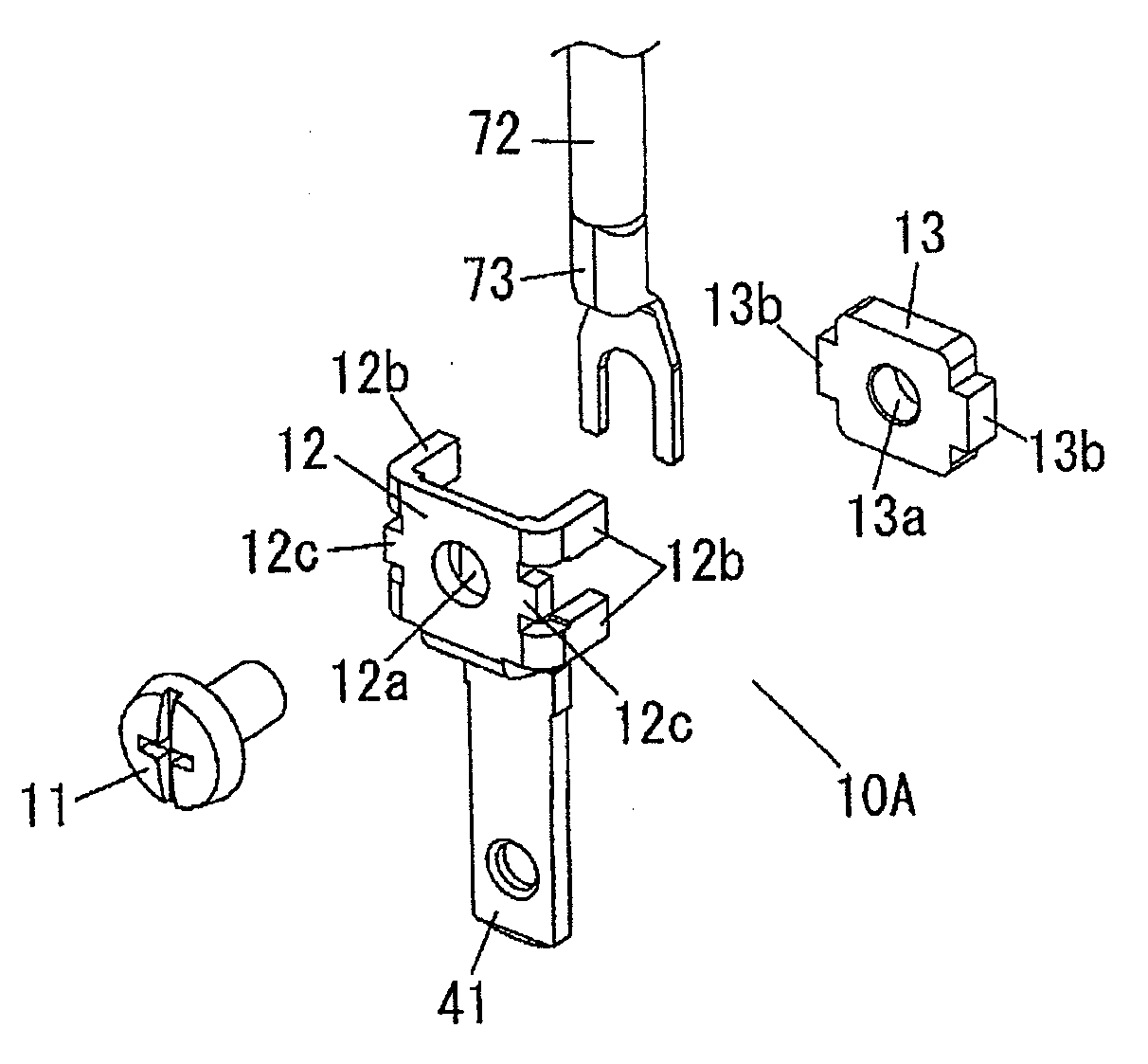
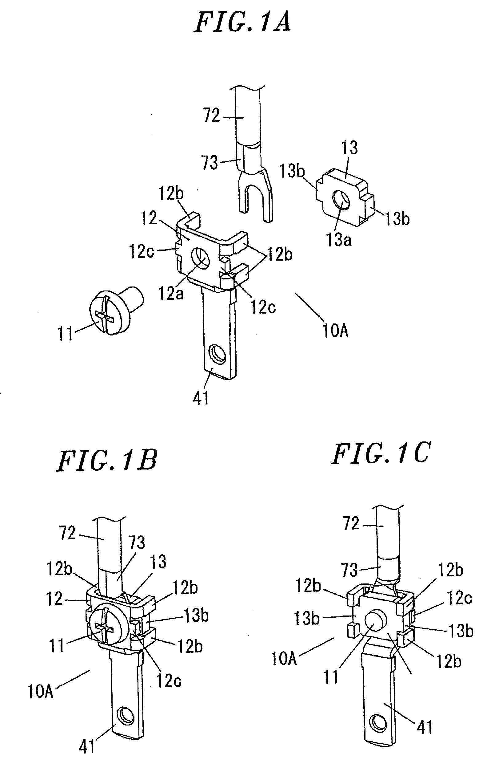
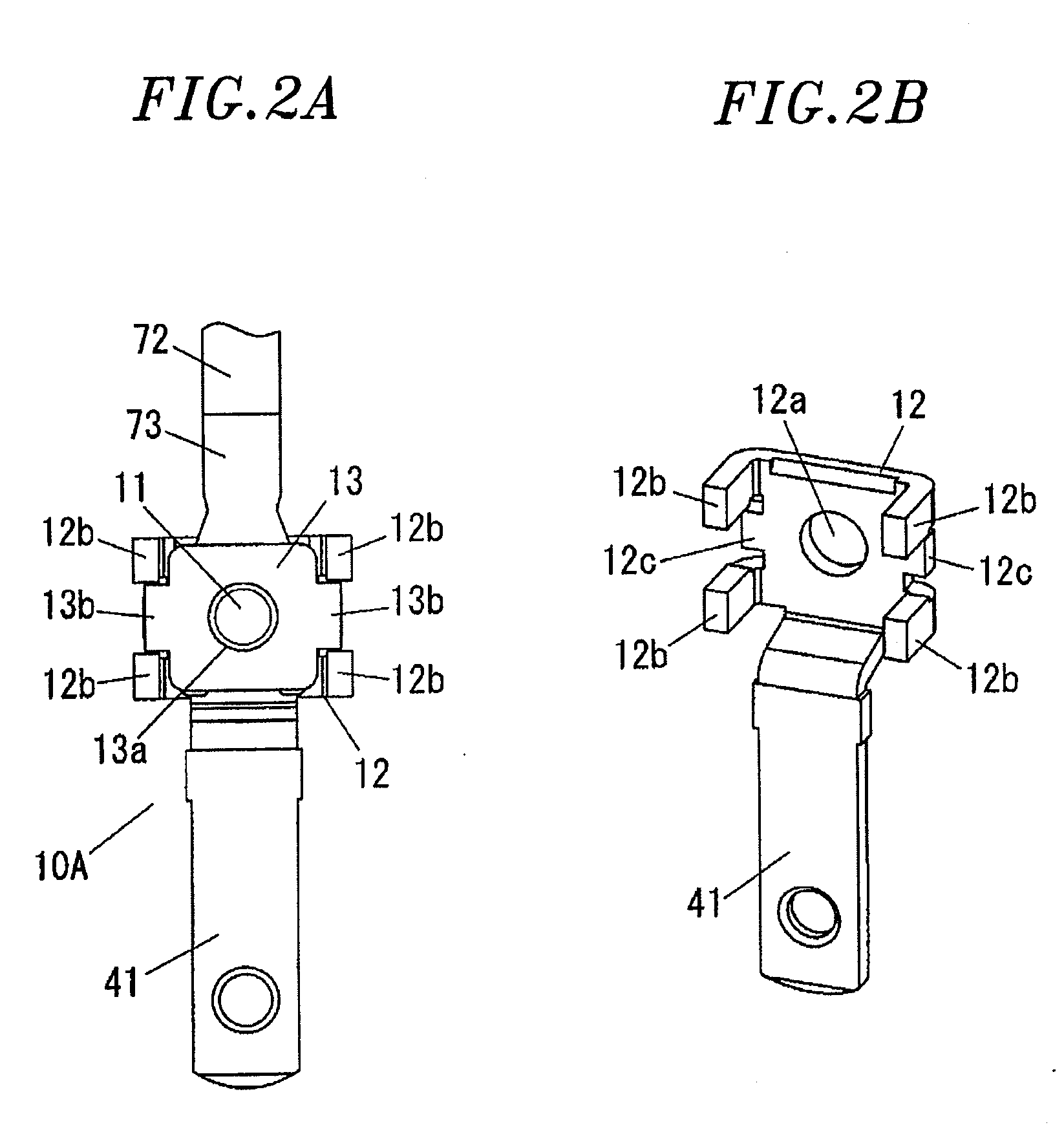
[0027]A screw terminal block in accordance with a first embodiment of the present invention will be described in detail with reference to FIGS. 1A to 5C. Note that, in the description of the screw terminal block, unless otherwise noted, up-down and right-left directions are defined based on the directions shown in FIG. 2A, and a front-rear direction is defined as a direction perpendicular to the sheet in FIG. 2A, but directions in which the screw terminal block 10A is actually used are not limited to the above directions.

[0028]The screw terminal block 10A includes: a terminal plate 12 provided with an insertion hole 12a through which a terminal screw 11 is to be inserted; and a fastening plate 13 provided with a screw hole 13a to which the terminal screw 11 inserted through the insertion hole is to be screwed.

[0029]The fastening plate 13 is formed into a substantially rectangular shape, when viewed from the front, by pressing a metal plate. Protrusions 13b are provided in central po...

second embodiment

[0043]An attachment plug in accordance with a second embodiment of the present invention will be described in detail with reference to FIGS. 6A to 11D. The attachment plug of the present embodiment, for example, used in a charging cable of an electric vehicle (including a hybrid electric vehicle and a plug-in hybrid electric vehicle), is connected to a receptacle of a charging station installed in a store, a business facility or the like, or a wall socket of a house. Note that, in the following description of the attachment plug, unless otherwise noted, a vertical direction in FIG. 6A is defined as an up-down direction, a horizontal direction in FIG. 6A is defined as a front-rear direction, and a vertical direction in FIG. 6B is defined as a right-left direction, but directions in which the attachment plug 1 is in use are not limited to the above directions.

[0044]The attachment plug 1 mainly includes a plug body 20, a triple of screw terminal blocks 10A, 10A and 10B, an electric wir...


PUM


Abstract

A screw terminal block 10A includes a terminal plate 12 provided with an insertion hole 12a through which a terminal screw 11 is inserted; and a fastening plate 13 provided with a screw hole 13a to which the terminal screw 11 inserted through the insertion hole 12a is screwed. The screw hole 13a is formed in the fastening plate 13, and a protrusion 13b is provided at right and left sides of the fastening plate 13. Upper and lower locking pieces 12b protruding toward the fastening plate 13 are provided at right and left side ends of the terminal plate 12 to sandwich the protrusion 13b therebetween. The locking piece 12b of the terminal plate 12 and the protrusion 13b of the fastening plate 13 are engaged with each other to restrict the relative rotation of the fastening plate 13 and the terminal plate 12.

Description

FIELD OF THE INVENTION[0001]The present invention relates to a screw terminal block and an attachment plug including the same.[0002]Conventionally, there is provided a screw terminal block, e.g., disclosed in Japanese Unexamined Utility Model Application Publication No. H03-26976, in which a screw terminal is disposed on a terminal base, the screw terminal being configured by screwing a terminal screw into a screw hole provided in a terminal plate. In this screw terminal block, a washer is interposed between a seating face of the terminal screw and the terminal plate. The washer comes into contact with a wall provided in the terminal base made of a resin, which makes it difficult to rotate the washer in conjunction with the terminal screw.[0003]In the screw terminal block disclosed in the above cited reference, a gap is provided between the wall disposed in the terminal base and the washer so as to allow the washer to move up and down as the terminal screw rotates, thereby enabling ...

Claims


Application Information

Patent Timeline
Patent Type & Authority Applications(United States)
IPC IPC(8): H01R4/36
CPCH01R4/42
Inventor ASAKUMA, YOSHIAKIKAWAMOTO, TAKASHITAKII, TOSHIYUKI
Owner PANASONIC CORP
Learn More