
Osmotic bioelectrochemical systems

a bioelectrochemical and osmotic technology, applied in biological water/sewage treatment, multi-stage treatment of water treatment, membranes, etc., can solve the problems of inability to use agricultural irrigation, lack of fresh water in sufficient quantities, and inability to meet the needs of industrial use,

Inactive Publication Date: 2013-01-17
UMW RES FOUND INC
View PDF2 Cites 44 Cited by
  • Summary
  • Abstract
  • Description
  • Claims
  • Application Information

AI Technical Summary

Benefits of technology

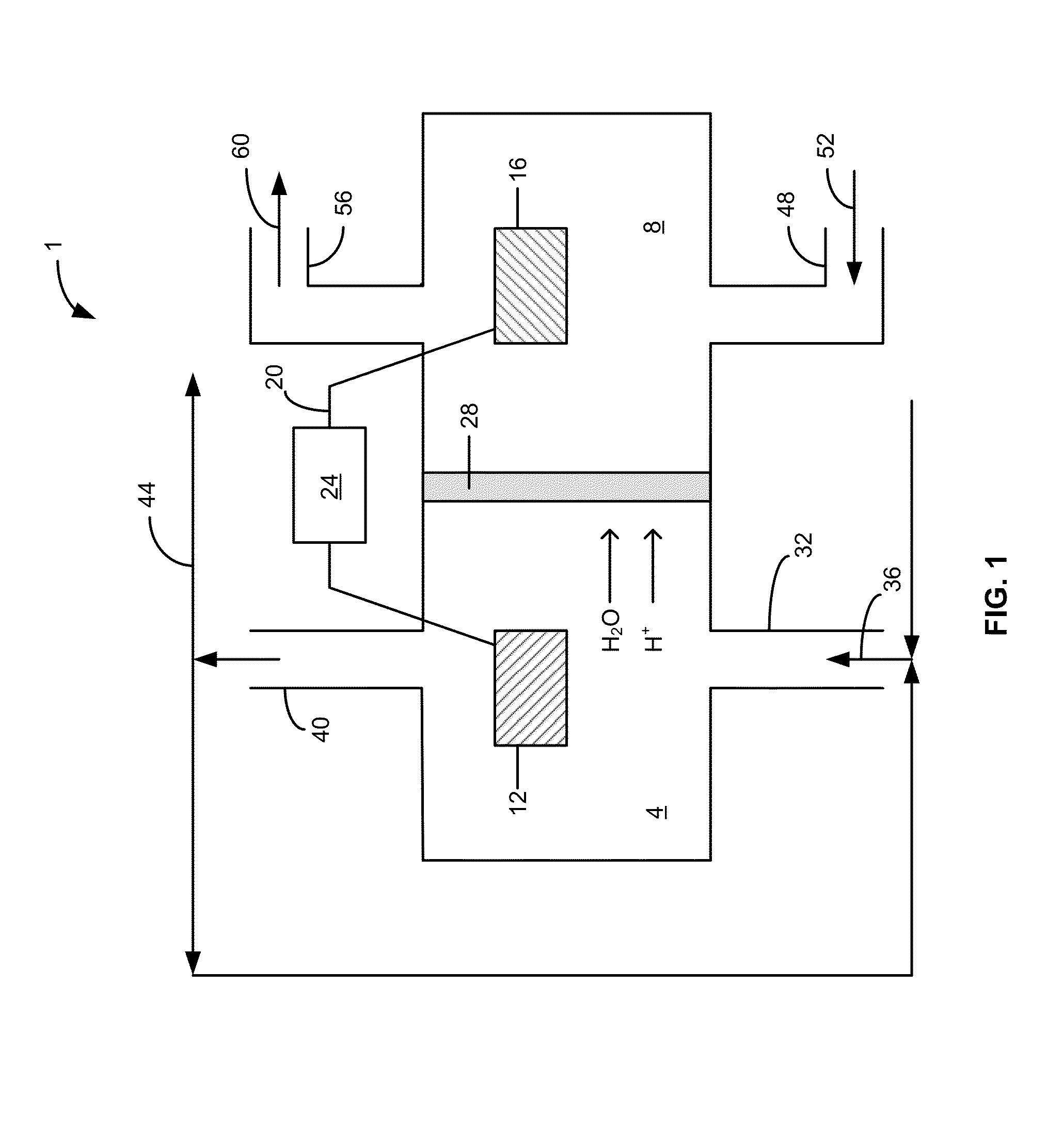
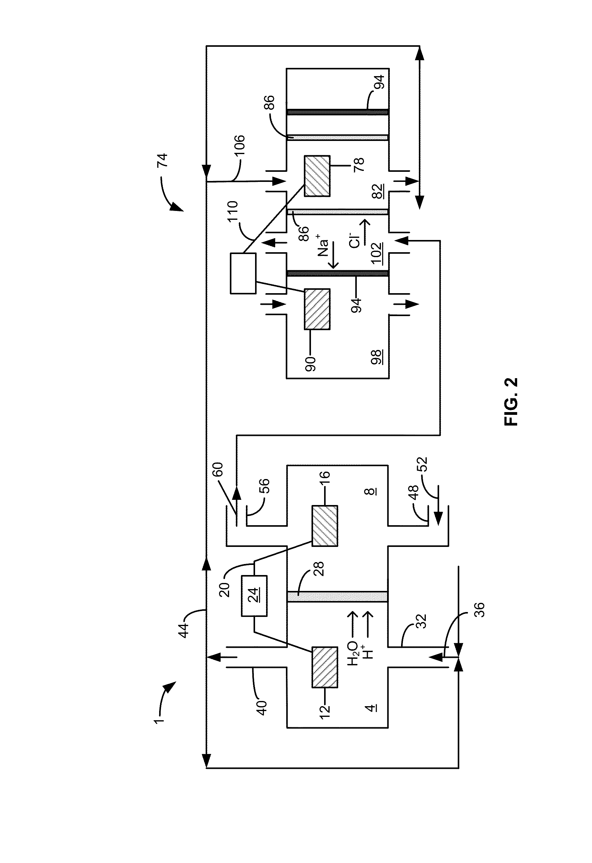
The patent discloses a system for treating water using bioelectrochemical processes. The system includes an anode, a saline solution chamber, and a cathode. The anode contains bacteria and an organic compound mixture, and the saline solution chamber receives a draw solution. The system works by delivering the organic compounds to the anode chamber, where they are oxidized by the bacteria, resulting in the movement of electrons from the anode to the cathode. The water treatment process also involves delivering the draw solution to the saline solution chamber, which is separated from the anode chamber by a membrane. Water diffuses across the membrane from the oxidized organic compounds to the draw solution, resulting in the dilution of the draw solution. The technical effects of this patent are the development of a system and process for efficiently treating water using bioelectrochemical methods.

Problems solved by technology

The lack of adequate quantities of fresh water poses a significant global challenge given that about 97% of the Earth's water is seawater.
Seawater is non-potable and cannot be used for agricultural irrigation.
Treatment of wastewater via forward osmosis, however, does not yield fresh water, but instead produces water still containing organic contaminants and thus the water is in need of further treatment.

Method used


Image

  • Osmotic bioelectrochemical systems
  • Osmotic bioelectrochemical systems
  • Osmotic bioelectrochemical systems

Examples


example 1

Integrating Forward Osmosis (FO) into a Microbial Fuel Cell (MFC) to Create an Osmotic Microbial Fuel Cell (OsMFC)

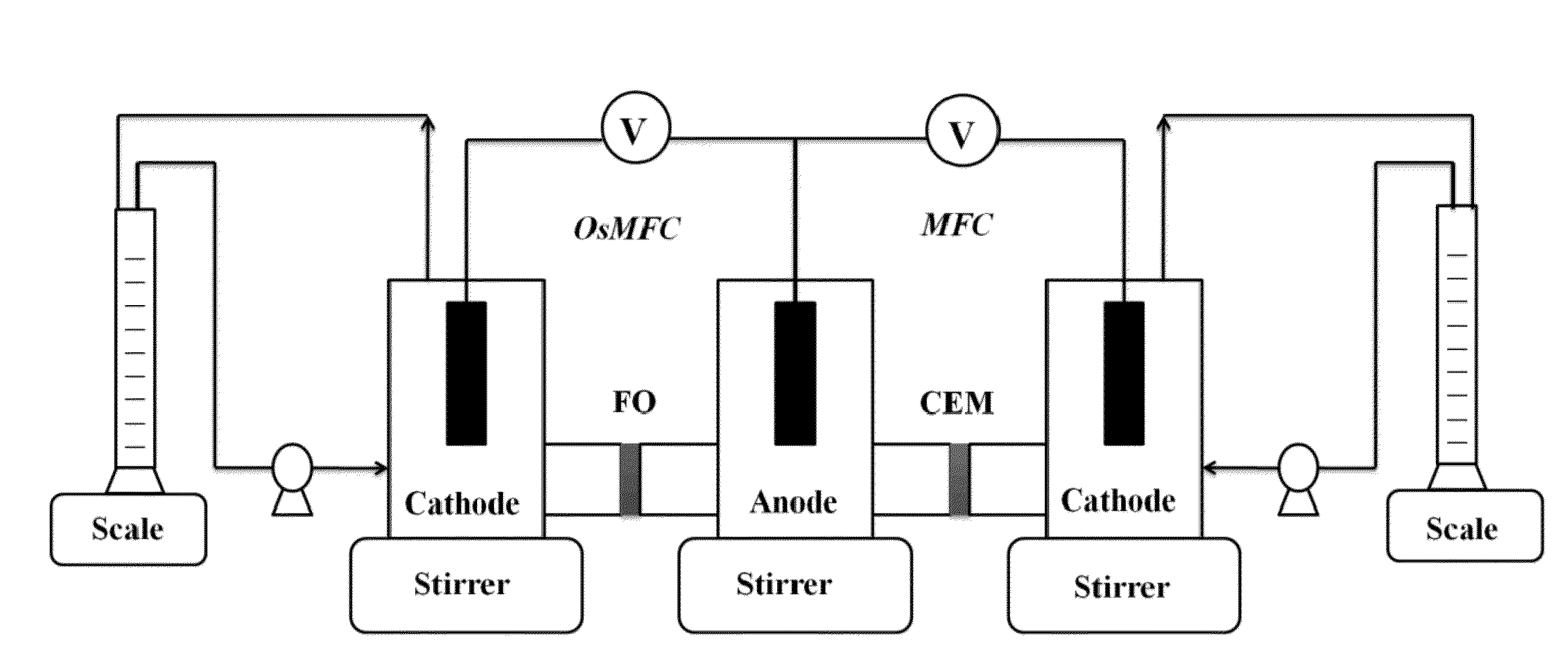
[0105]A three-compartment osmotic bioelectrochemical system was constructed that had two cathodes sharing the same anode, thereby creating two MFCs, namely, an OsMFC and a conventional MFC. The system was used to compare the performance of the OsMFC to the conventional MFC. By using such an arrangement, we expect to minimize the effect that a different anode may have on the experimental performance parameters. Electricity generation and water flux were examined with either NaCl solution or seawater as a catholyte (i.e., draw solution).

[0106]A. Materials and Methods

[0107]1. Osmotic Bioelectrochemical System Setup

[0108]The MFC system consisted of three equal-size compartments: two cathodes and one anode (FIG. 5). The total liquid volume of each compartment was 140 mL. The compartments were glass bottles jointed by either a forward osmosis (FO) membrane (Hydration Technolog...

example 2

Effects of Draw Solutions and Membrane Conditions on the Performance of OsMFCs

[0132]Draw solutions that are commonly used in FO processes were examined to determine their ability to function as catholytes for electricity production in an OsMFC. Additionally, the effects of membrane fouling were examined with regards to the performance of the OsMFC.

[0133]A. Materials and Methods

[0134]1. OsMFC Setup and General Operation

[0135]The OsMFC system consisted of two equal-size compartments including the anode and cathode (FIG. 12). The total liquid volume of each compartment was 140 mL. The liquid volume of the catholyte was 240 mL, including the cathode compartment and a flask attached to the cathode. The compartments were glass bottles connected by an FO membrane (Hydration Technology Innovations, LLC, Albany, Oreg., USA). Before use, FO membranes were soaked in deionized water for 30 min according to the manufacturer's instructions. For comparison, some studies replaced the FO membrane wi...

example 3

Reducing Effluent Discharge in an OsMFC

[0169]This study investigated the performance of an OsMFC treating actual domestic wastewater. Specifically, to examine an OsMFC's compatibility with more complex substrates, actual domestic wastewater was adapted. A synthetic acetate solution was still used to start up the OsMFC and to investigate the effect of recirculation rates. After a stable performance was achieved in acetate solution, the anode feeding solution was switched to domestic wastewater. Both electricity generation and water flux were monitored and the influence of hydraulic retention time was studied. Membrane fouling was characterized using electrochemical techniques and chemical analysis.

[0170]A. Materials and Methods

[0171]1. OsMFC Setup

[0172]The OsMFC consisted of two equal-size compartments (14×7×3.7 cm / each) as the anode and the cathode chambers, separated by an FO membrane (FIG. 18). The liquid volume of each compartment was 360 mL. Before use, the FO membrane (Hydratio...


PUM

PropertyMeasurementUnit
salt concentrationaaaaaaaaaa
sizeaaaaaaaaaa
sizeaaaaaaaaaa

Abstract

A bioelectrochemical system includes an anode, a saline solution chamber, and a cathode. The anode is at least partially positioned within an anode chamber containing an aqueous reaction mixture including one or more organic compounds and one or more bacteria for oxidizing the organic compounds. The saline solution chamber contains a draw solution and is separated from the anode chamber by a forward osmosis membrane. Water diffuses across the forward osmosis membrane from the aqueous reaction mixture to the draw solution.

Description

REFERENCE TO RELATED APPLICATION[0001]This application claims the benefit of U.S. Provisional Patent Application No. 61 / 506,223, filed Jul. 11, 2011 and U.S. Provisional Patent Application No. 61 / 585,509, filed Jan. 11, 2012, the contents of both of which are incorporated herein by reference in their entireties.BACKGROUND[0002]The lack of adequate quantities of fresh water poses a significant global challenge given that about 97% of the Earth's water is seawater. Seawater is non-potable and cannot be used for agricultural irrigation. As such, improved methods and systems for wastewater treatment and / or desalinating water may be critical for producing fresh water, especially in areas where seawater is abundant, but fresh water is not.[0003]A variety of technologies have been employed to produce fresh water from wastewater. One such technology is forward osmosis, which is the movement of water across a semi-permeable membrane in order to induce flow from an area of high-water potentia...

Claims


Application Information

Patent Timeline
Patent Type & Authority Applications(United States)
IPC IPC(8): C25B9/08H01M8/16C02F1/461C25B9/19
CPCC02F1/441B01D2311/25C02F3/005C02F3/341C02F2001/46138C02F2103/08C02F2201/003C02F2201/46115C02F2301/024C02F2301/08C02F2303/10C02F2303/16B01D61/002B01D61/025C02F1/445Y02W10/30Y02A20/131B01D2311/252
Inventor HE, ZHEN
Owner UMW RES FOUND INC
Learn More