Method of assembling and adjusting a multi-beam scanning optical apparatus and method of manufacturing a multi-beam scanning optical apparatus
- Summary
- Abstract
- Description
- Claims
- Application Information
AI Technical Summary
Benefits of technology
Problems solved by technology
Method used
Image

Examples
first embodiment
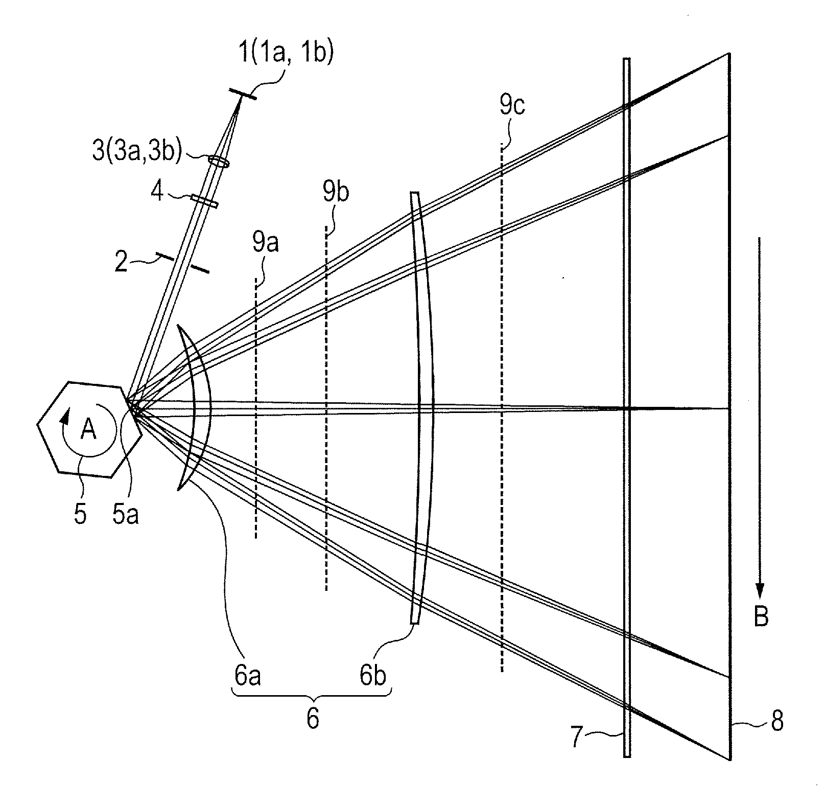
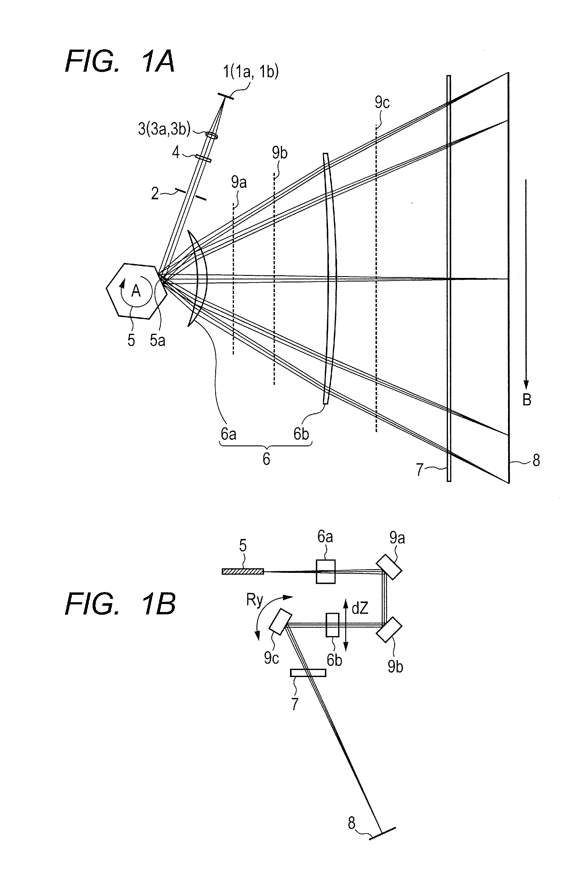
[0037]FIG. 1A is a view illustrating a main-scanning cross section of a scanning optical apparatus according to a first embodiment of the present invention. FIG. 1B is a view illustrating a sub-scanning cross section of the scanning optical apparatus according to the first embodiment of the present invention. The main scanning direction (Y direction) identifiable in this context is a direction perpendicular to a rotation axis of a deflecting unit 5 and an optical axis of an imaging optical system 6 (X direction) (a direction along which a light beam is deflected by the deflecting unit 5 (deflection scanning)). The sub-scanning direction (Z direction) identifiable in this context is a direction parallel to the rotation axis of the deflecting unit 5. The main-scanning cross section identifiable in this context is a plane including the optical axis of the imaging optical system 6 and the main scanning direction. The sub-scanning cross section identifiable in this context is a cross sec...
second embodiment
[0060]FIG. 12 is a diagram illustrating a sensor arrangement in a method of assembling and adjusting a multi-beam scanning optical apparatus according to a second embodiment of the present invention, in which elements assigned with the same reference symbols are the same as those described in the first embodiment. FIG. 13 is a flowchart of an assembling and adjusting process according to the second embodiment. The second embodiment is different from the first embodiment in that an optical sensor (e.g., a line CCD) 40 (second optical sensor) is arranged right in front of a toric lens 6b (on the deflecting unit side). Instead of evaluating the asymmetry by detecting an interval of the irradiated positions in the sub-scanning direction with optical sensors 21 and 23, a position of the light beam in the sub-scanning direction, which is entered into the toric lens 6b is detected with the optical sensor 40. If a detected incident position ΔZ in the sub-scanning direction is deviated by a ...
PUM
| Property | Measurement | Unit |
|---|---|---|
| Power | aaaaa | aaaaa |
| Height | aaaaa | aaaaa |
Abstract
Description
Claims
Application Information
 - R&D
- Intellectual Property
- Life Sciences
- Materials
- Tech Scout
- Unparalleled Data Quality
- Higher Quality Content
- 60% Fewer Hallucinations
Browse by: Latest US Patents, China's latest patents, Technical Efficacy Thesaurus, Application Domain, Technology Topic, Popular Technical Reports.
© 2025 PatSnap. All rights reserved.Legal|Privacy policy|Modern Slavery Act Transparency Statement|Sitemap|About US| Contact US: help@patsnap.com