Inspection jig and contact
a technology of inspection jigs and contacts, which is applied in the direction of measurement devices, printed circuit testing, instruments, etc., can solve the problems of increased contact area, difficult processing of insertion holes (reference numeral 34 of document 2) in the receiver pin, and increased cost, so as to facilitate insertion and adhesion, improve reliability of connection, and reliable conductive contact
- Summary
- Abstract
- Description
- Claims
- Application Information
AI Technical Summary
Benefits of technology
Problems solved by technology
Method used
Image
Examples
first embodiment
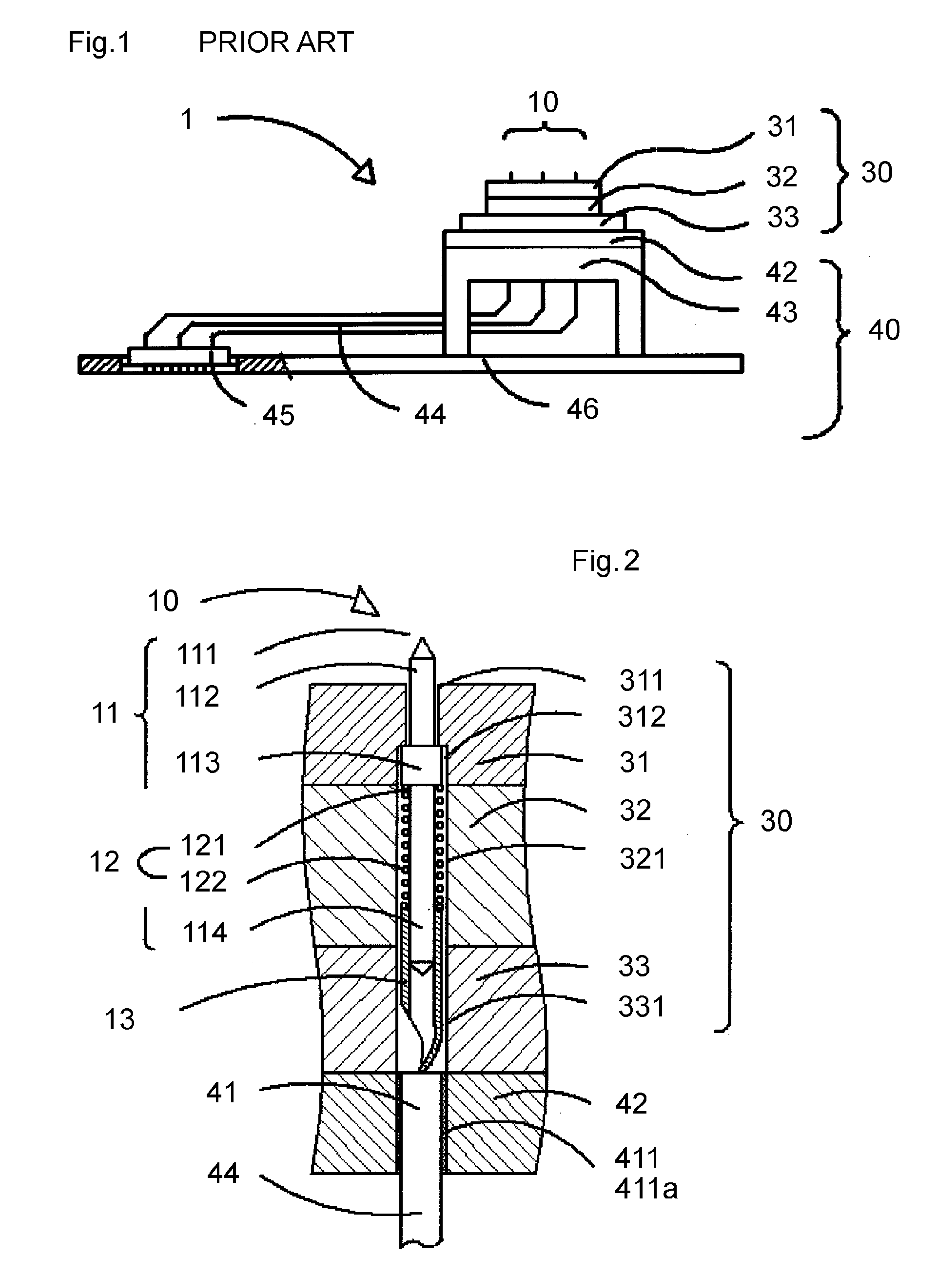
[0032]As depicted in FIG. 1, an inspection jig 1 using a contact 10 of the present invention has a plurality of contacts 10 held by a contact holder 30 to be detachably attached to an electrode plate 42. In the electrode plate 42, electrodes 41 as depicted in FIG. 2 are arranged coaxially with intermediate members 13 of the contacts 10 and secured to a support 43. The support 43 is secured to a jig base plate 46 together with connectors 45. The electrodes 41 and the connectors 45 are connected by leads 44 and constitute an electrode section 40. The inspection jig 1 is mounted on an inspection device to be electrically connected thereto by means of the connectors 45. The distal ends 111 of the contacts 10 pressingly contact inspection terminals of a printed circuit board to be inspected, thus allowing for measurement of electrical properties.
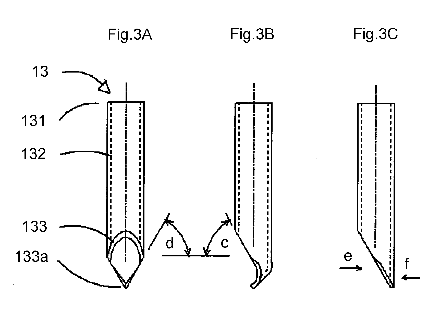
[0033]Description is given of an internal configuration with reference to FIG. 2. The contact 10 has a contact needle 11, a coil spring 12, and ...
second embodiment
[0047]Description is given with reference to FIG. 4. A contact needle 11a is formed of a bar-shaped member of 0.1 mm to 0.2 mm and has a projection 111, a coupling portion 115, and an intermediate portion 114 on the outer periphery of the bar-shaped member with the same outer diameter. A coil spring 12a is provided in the form of a coil spring 12a of a deformed wire with a rectangular wire cross section. The material thereof is beryllium copper herein. The coil spring 12a has an inner diameter slightly larger than the diameter of the bar-shaped member, and the endfaces of both ends are treated by open-loop polishing and have their cut sections at a right angle with respect to the axial direction. A stopping end 121 of the coil spring 12a is inserted in the coupling portion 115 that is at the position corresponding to the position of the larger diameter portion 113 and joined thereto by, for example, welding, such that the stopping end 121 serves a function of being stopped by a cont...
third embodiment
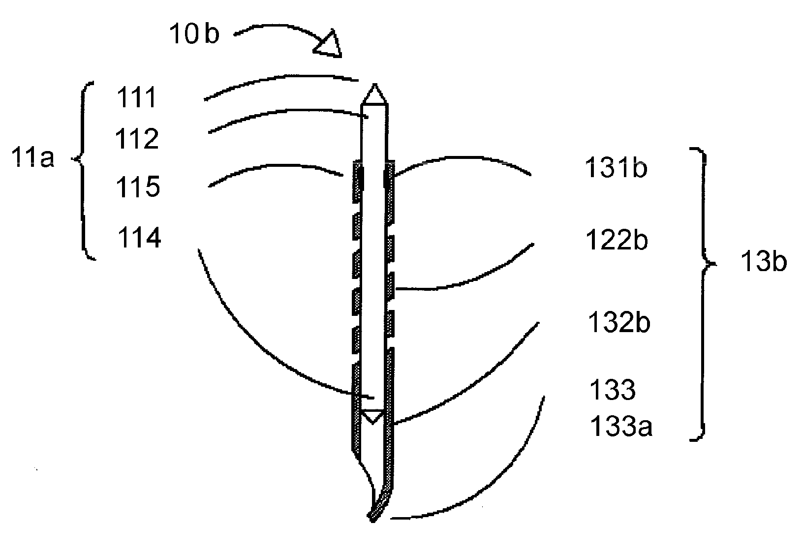
[0049]Description is given with reference to FIG. 6. The contact needle 11a is the same as that of the second embodiment. An intermediate member 13b is a conductive cylindrical member with an inner diameter slightly larger than the diameter of the contact needle 11a and includes an intermediate end 131b, a spring constant portion 122b, a guide portion 132b, an electrode end 133, and a proximal end 133a in a continuous manner. The spring constant portion 122b is provided continuously along a middle portion of the cylindrical member. The electrode end 133 constitutes the proximal end 133a through a similar process to that in the first embodiment. The intermediate end 131b is joined to the contact needle 10a at a position of the coupling portion 115 of the contact needle 10a by, for example, welding, so as to be stopped to and held by a contact holder 30 as in the second embodiment. In the present embodiment, the contact needle 11a and the intermediate member 13b are joined to each oth...
PUM
 Abstract
Description
Claims
Application Information
 - R&D
- Intellectual Property
- Life Sciences
- Materials
- Tech Scout
- Unparalleled Data Quality
- Higher Quality Content
- 60% Fewer Hallucinations
Browse by: Latest US Patents, China's latest patents, Technical Efficacy Thesaurus, Application Domain, Technology Topic, Popular Technical Reports.
© 2025 PatSnap. All rights reserved.Legal|Privacy policy|Modern Slavery Act Transparency Statement|Sitemap|About US| Contact US: help@patsnap.com


