
Energy management in a microwave cooking appliance

a technology for cooking appliances and energy management, applied in the field of energy management, can solve the problems of no active control, no peak shaving method for an appliance will provide maximum benefit, etc., and achieve the effect of reducing peak energy consumed by a microwave oven, and reducing peak power consumption

Inactive Publication Date: 2013-01-10
HAIER US APPLIANCE SOLUTIONS INC
View PDF23 Cites 13 Cited by
  • Summary
  • Abstract
  • Description
  • Claims
  • Application Information

AI Technical Summary

Benefits of technology

The patent text describes a method to reduce peak power consumption by a microwave oven by using a mechanism for reducing peak energy consumed by the oven. This is done by either the utility or the consumer shifting between normal power usage and reduced power usage during off-peak and peak demand periods, respectively. The mechanism allows for the use of a power source that shifts to an appropriate tap on the transformer to supply a lower voltage to the magnetron, resulting in lower peak power consumption without altering the duty cycle selected. This invention provides a less time- and development-intensive alternative to adjusting the cooking algorithm used by current microwave ovens.

Problems solved by technology

Currently utilities charge a flat rate, but with increasing cost of fuel prices and high energy usage at certain parts of the day, utilities have to buy more energy to supply customers during peak demand.
However, there is no active control beyond the mere on / off switching.
One difficulty is that no peak shaving method for an appliance will provide a maximal benefit.
Similarly, known systems do not communicate directly with the appliance using a variety of communication methods and protocols, nor is a modular and standard method created for communication devices to interface and to communicate operational modes to the main controller of the appliance.

Method used


Image

  • Energy management in a microwave cooking appliance
  • Energy management in a microwave cooking appliance
  • Energy management in a microwave cooking appliance

Examples


Embodiment Construction

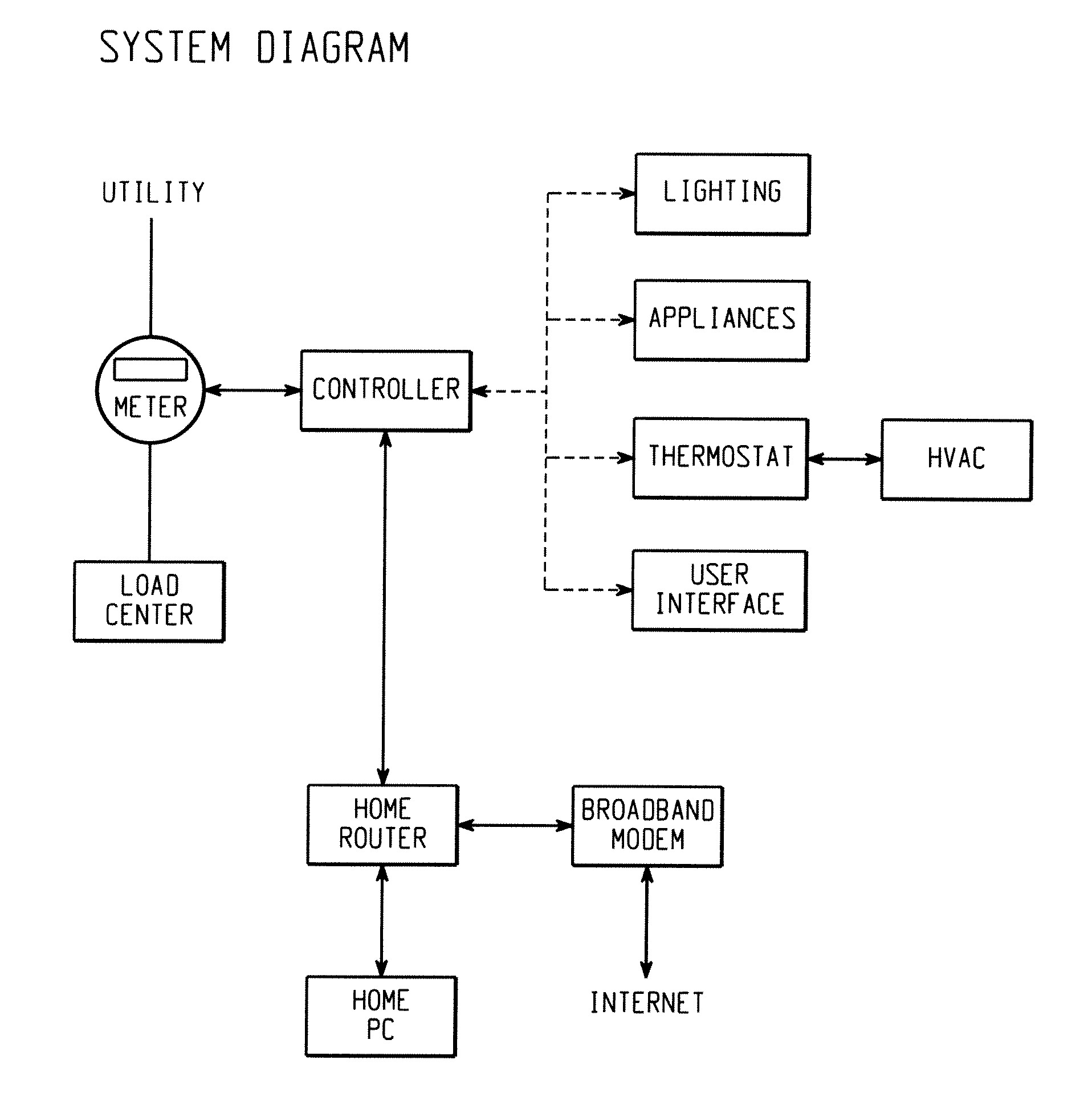
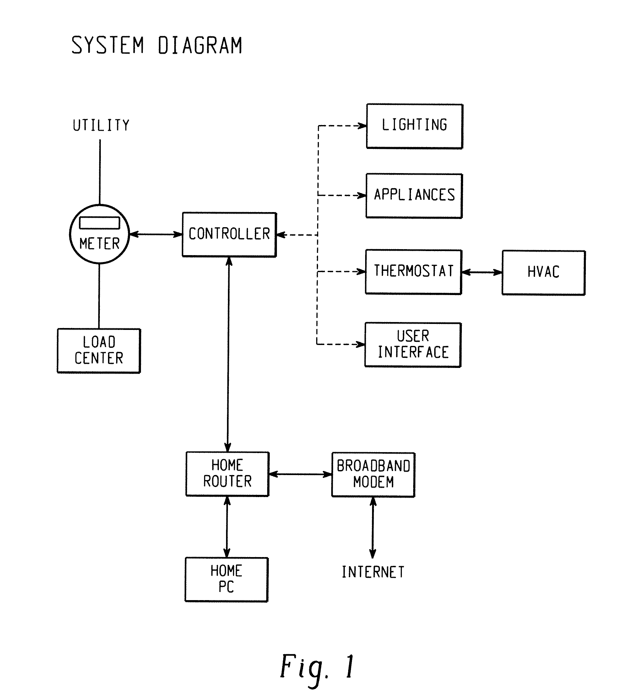
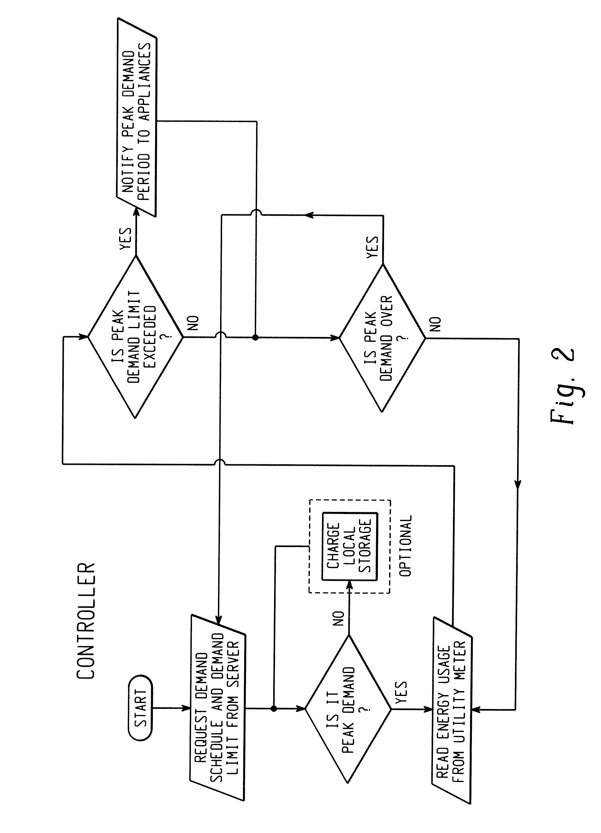
[0019]In one embodiment, a mechanism is provided to achieve power savings in a cooking appliance, such as a microwave oven, as well as to maintain the functionality and performance of the appliance while in the power saving mode. The power saving mode may be entered into in a number of ways, including but not limited to wireless, wired, voice-activated, push button, and any other common means of data transmitted protocols. The foregoing provides a more advanced system to handle energy management between the utility and the homeowner's appliances. The mechanism provided utilizes a multi-tap transformer such that when a signal is received by the controller, the appropriate tap on the transformer is engaged and the power saving mode is initiated. When in power saving mode, the appliance operates with full functionality, but on a lower voltage output. Therefore, the time necessary to complete a cooking cycle may be slightly increased. The use of the multi-tap transformer foregoes the ne...


PUM


Abstract

A microwave oven comprises a cooking cavity and a RF generation module configured to deliver microwave energy into the cooking cavity. A controller receives and processes a signal indicative of the current state of an associated energy supplying utility for determining whether to operate the microwave oven in one of a normal operating mode and a power saving mode in response to the received signal. A power source is operatively associated with the controller and the RF generation module, and is configured to receive a signal from the controller and cause the microwave oven to operate in normal operating mode or in power saving operating mode in accord with the signal.

Description

CROSS REFERENCE TO RELATED APPLICATIONS[0001]Cross-reference is made to commonly owned, copending application Ser. No. 12 / 559,705, filed 15 Sep. 2009 (Attorney Docket No. 238338 (GECZ 00997).BACKGROUND[0002]This disclosure relates to energy management, and more particularly to energy management of household consumer appliances. The disclosure finds particular application to changing existing appliances via add-on features or modules, and incorporating new energy saving features and functions into new appliances.[0003]Currently utilities charge a flat rate, but with increasing cost of fuel prices and high energy usage at certain parts of the day, utilities have to buy more energy to supply customers during peak demand. Consequently, utilities are charging higher rates during peak demand. If peak demand can be lowered, then a potential huge cost savings can be achieved and the peak load that the utility has to accommodate is lessened.[0004]One proposed third party solution is to provi...

Claims


Application Information

Patent Timeline
Patent Type & Authority Applications(United States)
IPC IPC(8): H05B6/68
CPCY02B40/143H05B6/6435H05B6/681H05B6/668H05B6/662Y02B40/00
Inventor LITTLE, DERRICK DOUGLASHENDRICKSON, SETHBOSTOCK, JONATHAN
Owner HAIER US APPLIANCE SOLUTIONS INC
Learn More