
transceiver

a transceiver and output technology, applied in the field of transceivers, can solve the problems of slow response of the vco, phase error signal on the output of the phase detector, frequency modulation of the vco,

Active Publication Date: 2013-01-03
QORVO INT PTE LTD
View PDF14 Cites 8 Cited by
  • Summary
  • Abstract
  • Description
  • Claims
  • Application Information

AI Technical Summary

Benefits of technology

The present invention is about a new method for reducing out-of-band frequency components in a control loop. By using a frequency locked loop with an improved loop filter, we can suppress the unwanted signals inside the loop. Compared to traditional PLLs, this method allows for better attenuation of out-of-band frequencies which results in a significant reduction in power consumption without compromising the loop bandwidth or causing a delay in settling. This method also uses standard components and is thus inexpensive and efficient. Additionally, this method offers a close-to-PLL mode with a short settling time and low power consumption.

Problems solved by technology

A phase difference will result in a phase error signal on the output of the phase detector.
Any noise on this signal naturally causes frequency modulation of the VCO.
Heavy filtering will make the VCO slow to respond to changes, causing drift and slow response time, but light filtering will produce noise and other problems with harmonics.
However, sampling introduces quantization and phase noise in the loop which is still found at the input of the VCO resulting in a VCO output signal with a frequency which generally is not stable enough for use in transceivers.
These components are rather power-consuming.
It is commonly known that sub-sampling enables to reduce the power consumption but it introduces quantization noise.
However, this will increase the settling time of the transceiver.
Generally, this is not done, mostly because there are noise disadvantages for example with respect to the in-band phase noise.
Practical aspects of a frequency synthesizer concern the amount of time during which the system can switch from channel to channel, time to lock when first switched on, and how much noise there is in the output.
(Any noise on this signal naturally causes frequency modulation of the VCO.).

Method used


Image

  • transceiver
  • transceiver
  • transceiver

Examples


Embodiment Construction

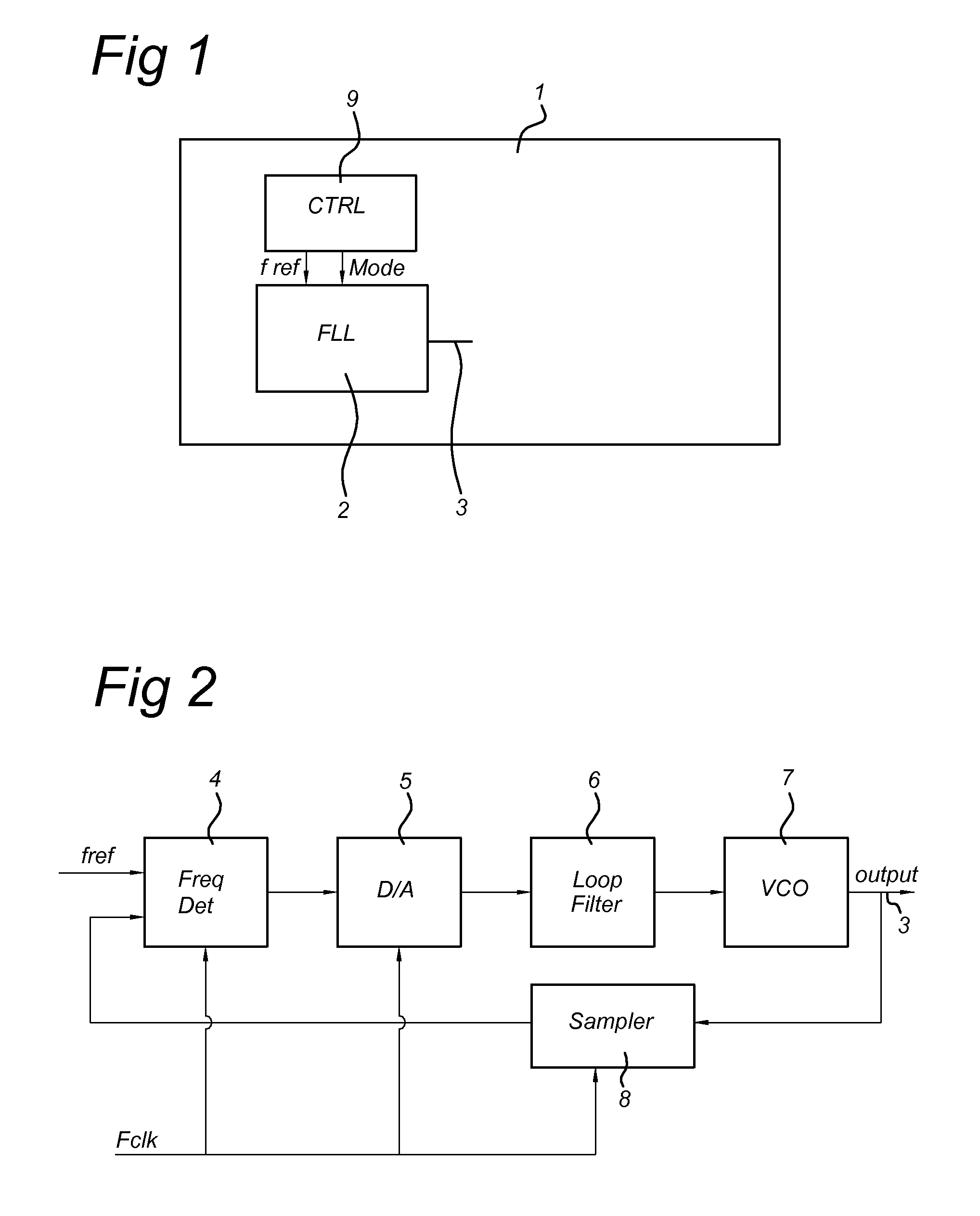
[0044]FIG. 1 shows a block diagram of a transceiver according to the invention. The transceiver 1 comprises a sub-sampling based FLL 2 configured to generate an output signal 3 for use as a carrier signal for transmission and / or a signal with channel frequency for reception and a control unit 9. The control unit 9 is configured to generate control signals to be supplied to the FLL 2. The control signals could be mode signals to set the mode of the FLL and other predetermined parameters to set the FLL, for example a parameter fref representing a reference frequency signal associated with the desired carrier frequency at the output 3 of the FLL 2. According to the invention and the following description the term “sub-sampling based” means that the output signal 3 of the frequency synthesizer having a frequency fout is sampled with a sampling unit with a sampling frequency fsampling to obtain a time discrete signal, wherein fsamplingout. By sub-sampling or under-sampling the frequency ...


PUM


Abstract

A transceiver 1 includes a frequency synthesizer 2 configured to generate an output signal 3 for use as a carrier signal for transmission and / or a signal with a channel frequency for reception, wherein the frequency synthesizer is a sub-sampling based frequency locked loop frequency synthesizer. The combination of a FLL and sub-sampling allows to obtain a sub-sample based locked loop with a closed loop response similar to a PLL but with improved settling time and improved suppression of high frequency components of the quantization noise due to the sampling process. The transceiver allows to obtain a frequency synthesizer with improved characteristics with respect to at least one of power consumption, locking characteristic, design optimization characteristics compared to non-sub-sampling PLL based frequency synthesizers.

Description

TECHNICAL FIELD OF THE INVENTION[0001]The invention relates to a transceiver, more particular to a transceiver with low power consumption, more particular to an IEEE 802.15.4 transceiver. The invention further relates to frequency synthesizer for use in a transceiver, more particular a frequency synthesizer with low power consumption, more particular to a frequency synthesizer for use in a IEEE 802.15.4 transceiver.BACKGROUND OF THE INVENTION[0002]Frequency synthesizers utilized in known radio frequency (RF) communication devices, such as a RF transmitter, have included a voltage controlled oscillator and a reference oscillator coupled together in a phase locked loop. A voltage-controlled oscillator or VCO is an electronic oscillator designed to be controlled in oscillation frequency by a voltage supplied to a control input. The frequency of oscillation fVCO depends on the applied DC voltage. The VCO frequency is divided by a 1 / N divider to a frequency comparable to a reference freq...

Claims


Application Information

Patent Timeline
IPC IPC(8): H04B1/40
CPCH03L7/091H03L7/06
Inventor VAN DRIEST, HANS
Owner QORVO INT PTE LTD
Learn More