Luminaire and louver

a technology of louvers and luminaires, applied in the field of luminaires, can solve the problems of non-uniform luminance and led spread ou

Inactive Publication Date: 2012-12-27
SIGNIFY HLDG BV +1
View PDF3 Cites 6 Cited by
  • Summary
  • Abstract
  • Description
  • Claims
  • Application Information

AI Technical Summary

Benefits of technology

[0009]In an embodiment the converging means are placed in between the lamellae, i.e. in an interdigitated configuration, thus preventing the light rays propagating along the light emission window from mutually spreading at too wide an angle. Preferably each converging means is equally spaced from its neighboring lamellae, thus providing the luminaire with a pleasant appearance. The converging means can be a reflective element, for example one or a plurality of elongated, concave, paraboloidally curved reflectors, or a refractive element, for example one or a plurality of normal lenses or Fresnel lenses. Fresnel lenses are easy-to-manufacture, light-weight flat lenses which require only little material, thus offering the advantage of material savings in the manufacture of the luminaire. It is convenient for the luminaire to comprise a housing.
[0010]As a further embodiment, it is also possible to combine the mirror and lens functions into a single element. Here, the element can have, e.g. on the front surface, semi-diffusely reflecting patches while the back surface has a Fresnel lens structure. Thus, a relatively simple, light-weight and compact lamellae structure is enabled.
[0011]The direction of the beam issued by the luminaire can be adjusted by tilting the lamellae. Preferably each lamella is tiltable independently of other lamellae with respect to the light emission window in an angle range of α, for example, 35° to 55°, thus enabling further control of beam shape and beam direction of light issuing from the luminaire. The beam width and beam shape may be further adjusted by replacing the lamellae with lamellae that have different (e.g. asymmetric) scattering properties, or by shifting lamellae with respect to each other, such that (most of the) light hits a different region on the lamella with different scattering properties, for example by aligning or de-aligning the perforation patterns of neighboring lamellae.
[0013]In an embodiment the luminaire is characterized in that the lamellae holding means is chosen from the group consisting of a (tension) wire, a (removable) rim, a housing, a (parabolic) reflector. This enables the luminaire to consist of only the electrical contact, and a set of lamellae kept in place by wires under tension, or by a rigid rim to which optionally the light source, and / or a (parabolic) reflector and / or a housing can be added. The advantage is that the luminaire is light and transparent and that, by removing the rim or loosening the tension on the wires, the lamellae can be folded or stacked together, which makes the luminaire foldable and / or very compact for transportation. Another advantage of such “foldable” luminaries without fixed back reflector / housing is that the number of lamellae or the spacing may be varied, such that a luminaire of variable size may be achieved.

Problems solved by technology

One of the disadvantages of high brightness light sources is that they easily result in non-uniform luminance, while for office applications a light source with a uniform lower brightness is required.
The disadvantage however is that this requires the LEDs to be spread out in the luminaire.

Method used


Image

  • Luminaire and louver
  • Luminaire and louver
  • Luminaire and louver

Examples


first embodiment

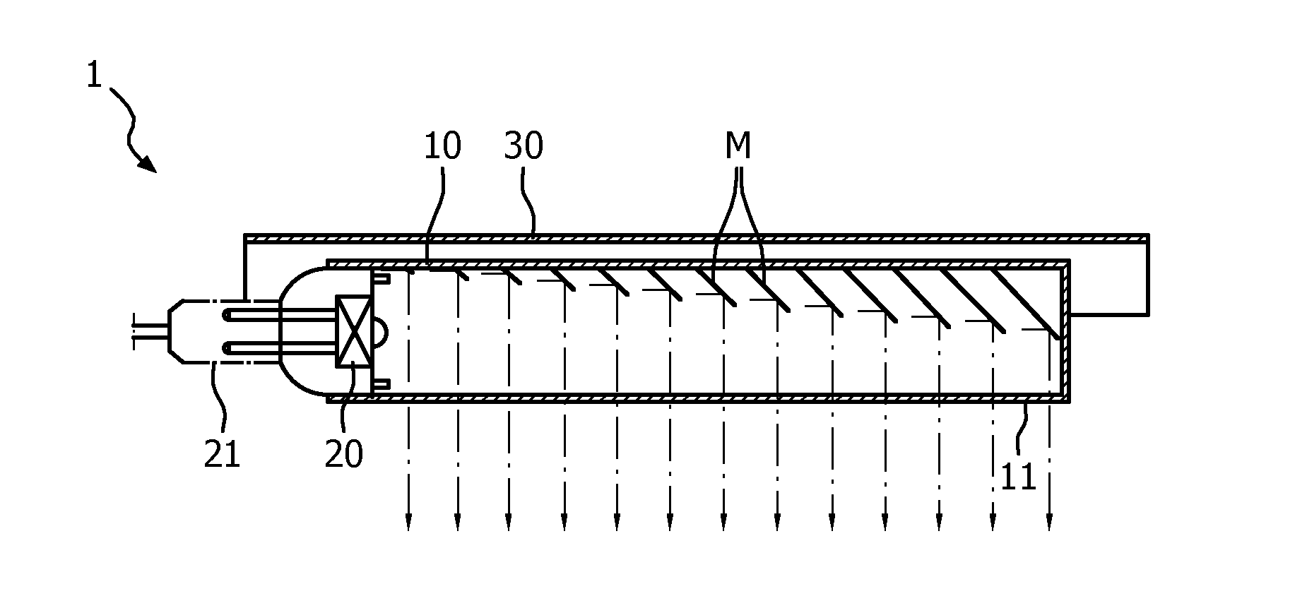
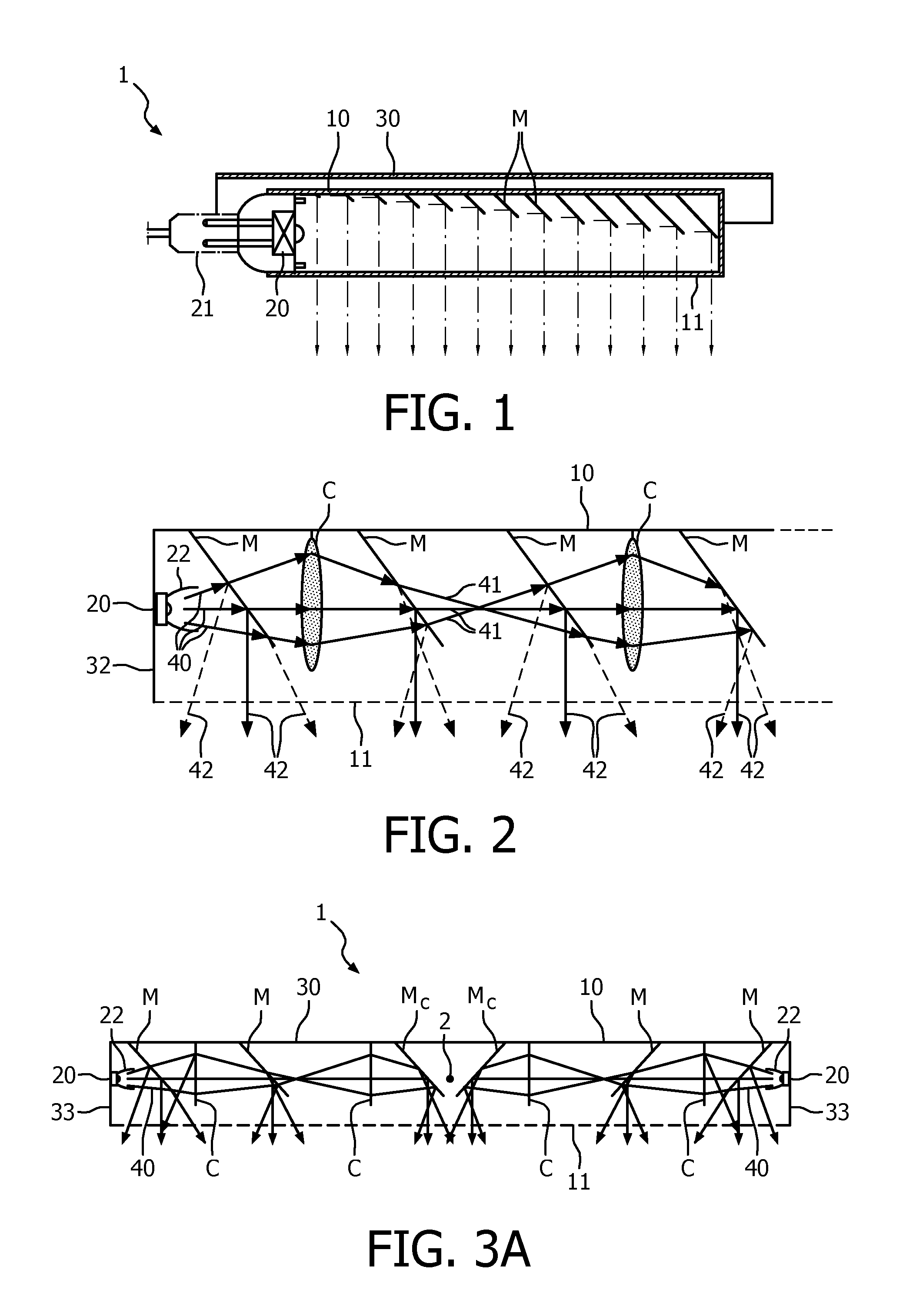
[0019]FIG. 2 shows a cross sectional side view of a luminaire according to the invention;

second embodiment

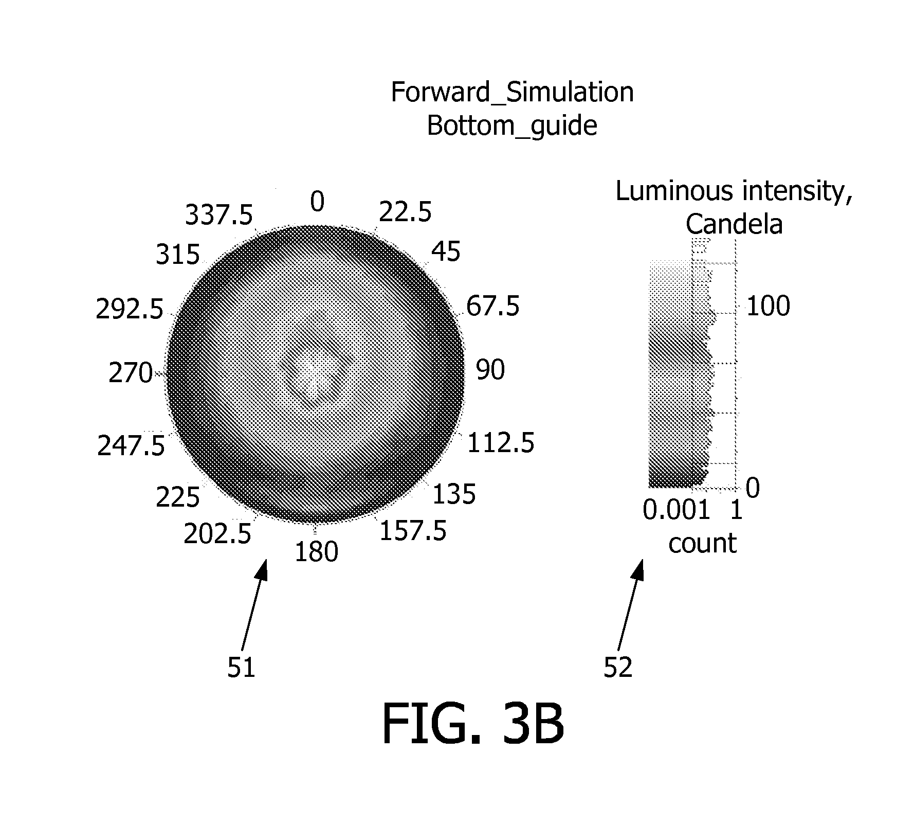
[0020]FIG. 3A shows a cross sectional side view of a part of a luminaire according to the invention;

[0021]FIG. 3B shows a calculated illuminance plot as obtained by the luminaire of FIG. 3A;

third embodiment

[0022]FIG. 4A shows a cross sectional side view of a luminaire according to the invention;

[0023]FIG. 4B shows a perspective view of the luminaire of FIG. 4A;

[0024]FIG. 4C shows a detail of the luminaire of FIG. 4A;

[0025]FIG. 4D shows a calculated illuminance plot as obtained by the luminaire of FIG. 4A.


PUM


Abstract

A luminaire comprising lamellae holding means, a light source, and a set of lamellae comprising a plurality of (inclined) lamellae. The set of lamellae extends at least partially over a light emission window. The lamellae have a reflective front surface facing towards the light source, said front surface being designed to partially reflect light to the exterior and partially transmit light, for example in that the lamellae are diffusely translucent or have a perforated surface. The set of lamellae is provided with light converging means, for example a Fresnel lens, which optionally are integrated in the lamellae to prevent the luminaire becoming too bulky.

Description

FIELD OF THE INVENTION[0001]The invention relates to a luminaire comprising[0002]at least one electrical contact for accommodating at least one light source;[0003]a set of lamellae held by lamellae holding means which are arranged adjacent and / or opposite a light exit window, the set of lamellae comprising a plurality of lamellae in an inclined position with respect to the light emission window, the set of lamellae extending at least partially alongside the light emission window;[0004]each lamella having a front surface facing towards a respective light source, said front surface being designed to partially intercept light and direct the intercepted light via the light emission window to the exterior, and to partially transmit light and allow light originating from said respective light source to propagate further alongside the light emission window.[0005]The invention further relates to a louver.BACKGROUND OF THE INVENTION[0006]Such a luminaire is known from KR2009083546. The known...

Claims


Application Information

Patent Timeline
Patent Type & Authority Applications(United States)
IPC IPC(8): F21V11/02F21V7/00F21V13/04F21V5/04F21V9/40F21Y101/00
CPCF21V5/04F21V5/045F21V7/0008F21V7/0025F21Y2101/02F21V9/10F21V11/14F21V13/04F21V7/05F21Y2115/10F21V9/45F21V5/10
Inventor VAN GORKOM, RAMON PASCALVISSENBERG, MICHEL CORNELIS JOSEPHUSHAENEN, LUDOVICUS JOHANNES LAMBERTUS
Owner SIGNIFY HLDG BV
Why Eureka
Try Eureka