Eureka AIR delivers breakthrough ideas for toughest innovation challenges, trusted by R&D personnel around the world.

Method and apparatus for measuring magnetic parameters of magnetic thin film structures

a thin film structure and magnetic parameter technology, applied in the direction of magnetic measurement, instruments, measurement devices, etc., can solve the problems of time and resources consumption of both methods, and achieve the effect of little or no processing

Active Publication Date: 2012-12-27
AVALANCHE TECH
View PDF2 Cites 33 Cited by
  • Summary
  • Abstract
  • Description
  • Claims
  • Application Information

AI Technical Summary

Benefits of technology

The present invention provides a measurement technique and corresponding devices for extracting magnetic parameters of damping of magnetization precession, magnetic anisotropy, and saturation magnetization of thin film stacks, such as MTJs, with little or no processing. The technique involves using probe tips to position two oscillating current sequences on the unpatterned film stack to induce small oscillations of the magnetizations of the magnetic layers and measuring the resulting voltage. The resonance frequencies of magnetization precession in the magnetic films can be determined by measuring the voltage generated at different frequencies. The technique can be used to extract the damping parameter of the individual magnetic layers by inducing small oscillations of the magnetizations and measuring the resulting voltage. The invention also provides an apparatus for inducing high-frequency oscillating currents and measuring the resulting voltage. Additionally, the invention provides a method for extracting the DC voltage from an AC signal using a low-frequency lock-in technique. The invention can also be used to extract the magnetic anisotropy and saturation magnetization of the magnetic layers by applying a selected magnetic field to the sample.

Problems solved by technology

Both of these methods are costly in time and resources.

Method used


Image

  • Method and apparatus for measuring magnetic parameters of magnetic thin film structures
  • Method and apparatus for measuring magnetic parameters of magnetic thin film structures
  • Method and apparatus for measuring magnetic parameters of magnetic thin film structures

Examples


Embodiment Construction

[0017]In the following description of the embodiments, reference is made to the accompanying drawings that form a part hereof, and in which is shown by way of illustration of the specific embodiments in which the invention may be practiced. It is to be understood that other embodiments may be utilized without departing from the scope of the present invention. It should be noted that the figures discussed herein are not drawn to scale and thicknesses of lines are not indicative of actual sizes.

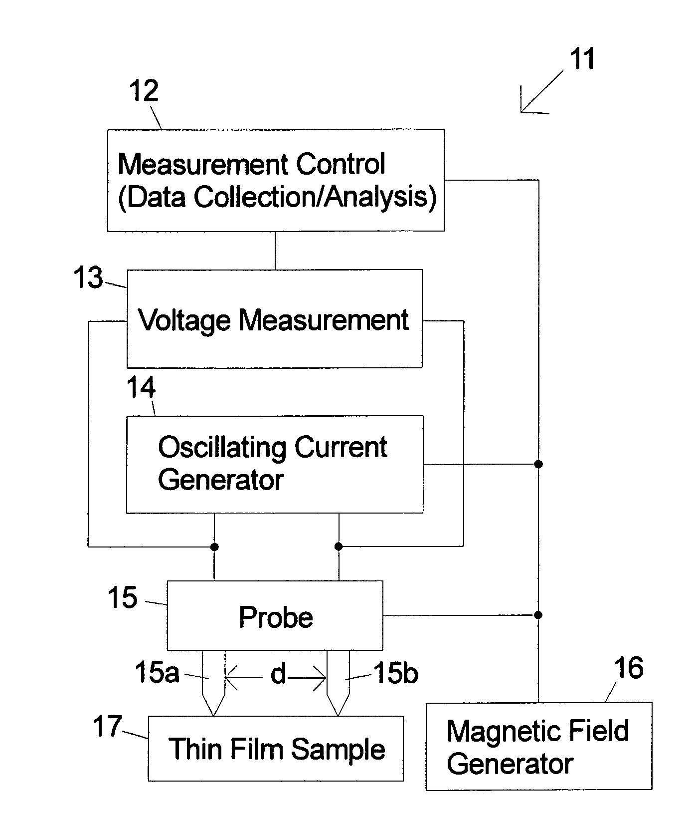
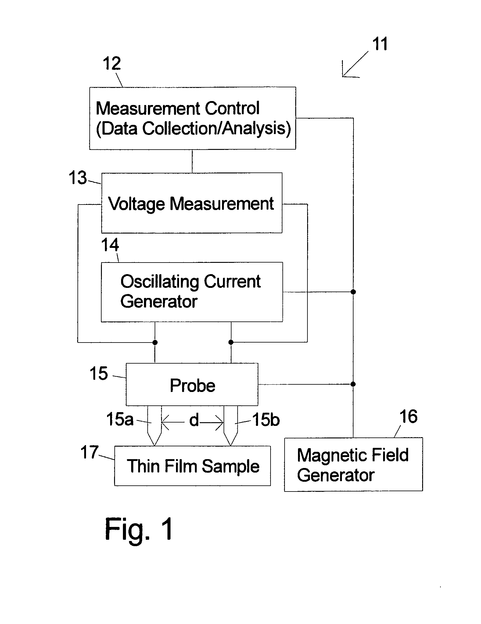
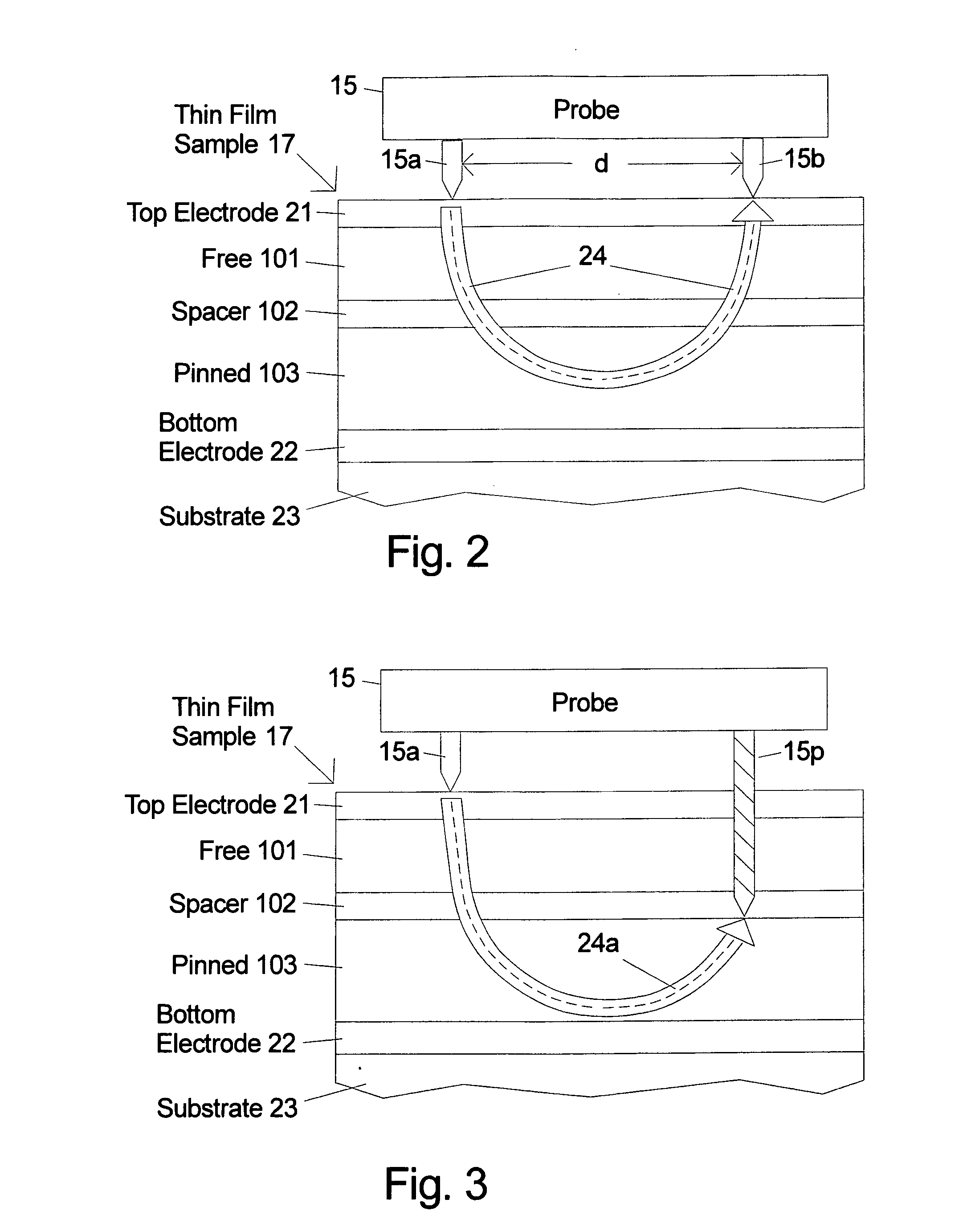
[0018]FIG. 1 is an illustration of selected components in an apparatus 11 for measuring magnetic parameters of thin film sample 17 including damping of magnetization precession, magnetic anisotropy and saturation magnetization according to embodiments of the invention. It is an advantage of the invention that magnetic parameters can be obtained in the thin films on a substrate or wafer that is unpatterned (blanket) with little or no processing. An embodiment of the invention will be described t...


PUM


Abstract

High-frequency resonance method is used to measure magnetic parameters of magnetic thin film stacks that show magnetoresistance including MTJs and giant magnetoresistance spin valves. The thin film sample can be unpatterned. Probe tips are electrically connected to the surface of the film (or alternatively one probe tip can be punched into the thin film stack) and voltage measurements are taken while injecting high frequency oscillating current between them to cause a change in electrical resistance when one of the layers in the magnetic film stack changes direction. A measured resonance curve can be determined from voltages at different current frequencies. The damping, related to the width of the resonance curve peak, is determined through curve fitting. In embodiments of the invention a variable magnetic field is also applied to vary the resonance frequency and extract the magnetic anisotropy and / or magnetic saturation of the magnetic layers.

Description

FIELD OF THE INVENTION [0001]The present invention relates to the measurement of characteristic parameters (e.g. damping of magnetization precession, magnetic anisotropy and saturation magnetization) of magnetic thin films stacks that show magnetoresistance including magnetic tunnel junctions (MTJ) and giant magnetoresistance spin valves. More particularly, the invention relates to making such magnetic measurements on unpatterned (blanket) thin film layer stacks.BACKGROUND OF THE INVENTION[0002]Magnetization dynamics is a key aspect of how magnetic technology based devices function. How the magnetization precesses around the effective magnetic field and how this precession is damped influences how fast and how energetically efficient a magnetic memory bit is switched in magnetoresistive random access memory (MRAM). The important magnetic parameters that describe these processes are the damping coefficient, intrinsic magnetic anisotropy, saturation magnetization.[0003]A lot of resear...

Claims


Application Information

Patent Timeline
Patent Type & Authority Applications(United States)
IPC IPC(8): G01R33/02
CPCG01R33/093
Inventor TUDOSA, IOANZHOU, YUCHENZHANG, JINGRANJAN, RAJIV YADAVHUAI, YIMING
Owner AVALANCHE TECH
Why Eureka
Eureka Blog
Learn More