Stator manufacturing method, stator, and motor

a manufacturing method and stator technology, applied in the direction of windings, synchronous machines with stationary armatures, windings, etc., can solve the problems of reducing the area that can be occupied by windings, reducing the occupancy rate, and difficult deformation and narrowing of insulating members in the circumferential direction of slots, so as to achieve the effect of not lowering the occupancy ra

Inactive Publication Date: 2012-12-27
ASMO CO LTD
View PDF3 Cites 10 Cited by
  • Summary
  • Abstract
  • Description
  • Claims
  • Application Information

AI Technical Summary

Benefits of technology

[0006]It is an object of the present invention to provide a stator manufacturing method, a stator, and a motor that ensure insulation between the conductor and the armature core without lowering in the occupancy rate.

Problems solved by technology

This reduces the area that can be occupied by a winding and thereby lowers the occupancy rate.
This makes it difficult to deform and narrow the insulating member in the circumferential direction of the slot.
Thus, it becomes difficult to insert the insulating member into the slot without rubbing the insulating member against the wall surface of the slot.
When the insulating member is rubbed against an open edge of the slot in the axial direction or the wall surface of the slot, the insulating property of the insulating member may be deteriorated.
However, the thick insulating member may lower the occupancy rate.

Method used


Image

  • Stator manufacturing method, stator, and motor
  • Stator manufacturing method, stator, and motor
  • Stator manufacturing method, stator, and motor

Examples


Embodiment Construction

[0028]One embodiment of the present invention will now be described with reference to the drawings.

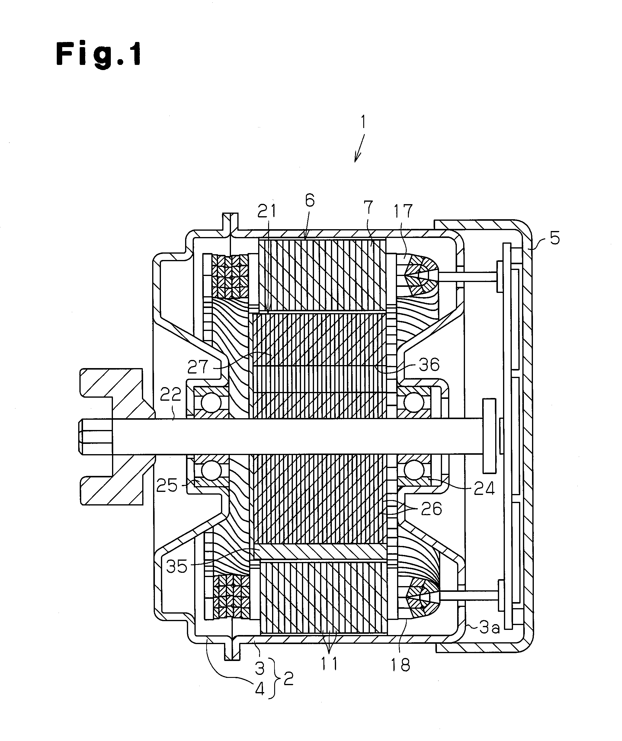
[0029]As shown in FIG. 1, a motor 1 includes a motor case 2 formed by a tubular housing 3, which has a closed end, and a front end plate 4, which closes an open front side (left side in FIG. 1) of the tubular housing 3. A circuit accommodating box 5, which accommodates circuit substrates such as a power supply circuit, is attached to rear side (right side in FIG. 1) of the tubular housing 3.

[0030]A stator 6 is fixed to an inner circumferential surface of the tubular housing 3. The stator 6 includes an armature core 7. The armature core 7 is formed by stacking a plurality of plate-shaped core sheets 11, which are formed from steel plates. As shown in FIG. 2, the armature core 7 includes an annular portion 12 and a plurality of teeth 13 arranged along a circumferential direction. Each tooth 13 extends inward in a radial direction from the annular portion 12. The armature core 7 of the pr...


PUM

PropertyMeasurementUnit
widthaaaaaaaaaa
lengthaaaaaaaaaa
specific gravityaaaaaaaaaa

Abstract

A stator manufacturing method includes the steps of preparing an armature core, forming an insulating member including two opposing portions from a sheet-like insulating material, and deforming the insulating member to move the two opposing portions toward each other. The method also includes the step of inserting distal parts of the two opposing portions into the corresponding slit from the axial direction thereby covering an inner surface of each of the slot with the insulating member. Further, the method includes the steps of inserting a conductor forming a winding into each of the slots between the two opposing portions.

Description

BACKGROUND OF THE INVENTION[0001]The present invention relates to a stator manufacturing method, a stator, and a motor including the stator.[0002]A known stator for a motor includes segment conductor (SC) windings. Such a stator includes an insulating member arranged between a conductor, which forms a winding, and an armature core to ensure insulation between the conductor and the armature core. It is known that a stator including SC windings increases the occupancy rate of windings.[0003]Japanese Laid-Open Patent Publication No. 2000-308314 describes a stator including sheet-like insulating members. An armature core of such a stator includes a plurality of slots arranged along the circumferential direction. A slit is formed inward in the radial direction from each slot. The slit has a smaller width in the circumferential direction than the slot. Each slit opens to the interior of the corresponding slot and the radially inward side of the armature core. The insulating member is tubu...

Claims


Application Information

Patent Timeline
Patent Type & Authority Applications(United States)
IPC IPC(8): H02K21/14H02K15/085H02K3/34
CPCH02K21/14H02K1/278Y10T29/49009H02K15/0018H02K3/12
Inventor KINPARA, YOSHIMASAKANEMATSU, YASUHIRO
Owner ASMO CO LTD
Why Eureka
Try Eureka