
Rigid-endoscope oversheath

a technology of endoscope and ejection port, which is applied in the field of rigidendoscope oversheath, can solve problems such as the increase in the size of the ejection por

Inactive Publication Date: 2012-12-13
FUJIFILM CORP
View PDF4 Cites 38 Cited by
  • Summary
  • Abstract
  • Description
  • Claims
  • Application Information

AI Technical Summary

Benefits of technology

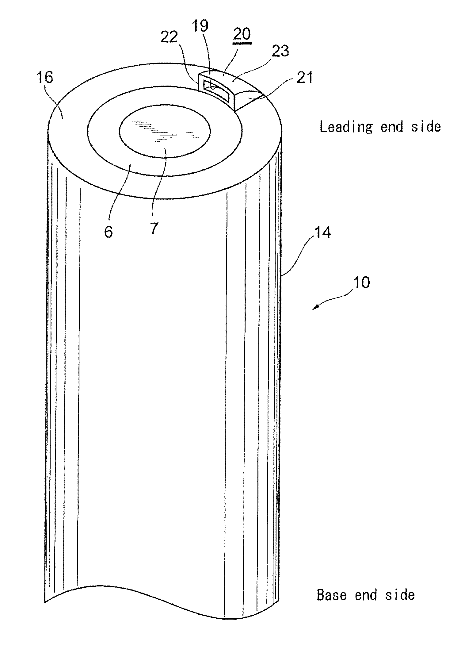
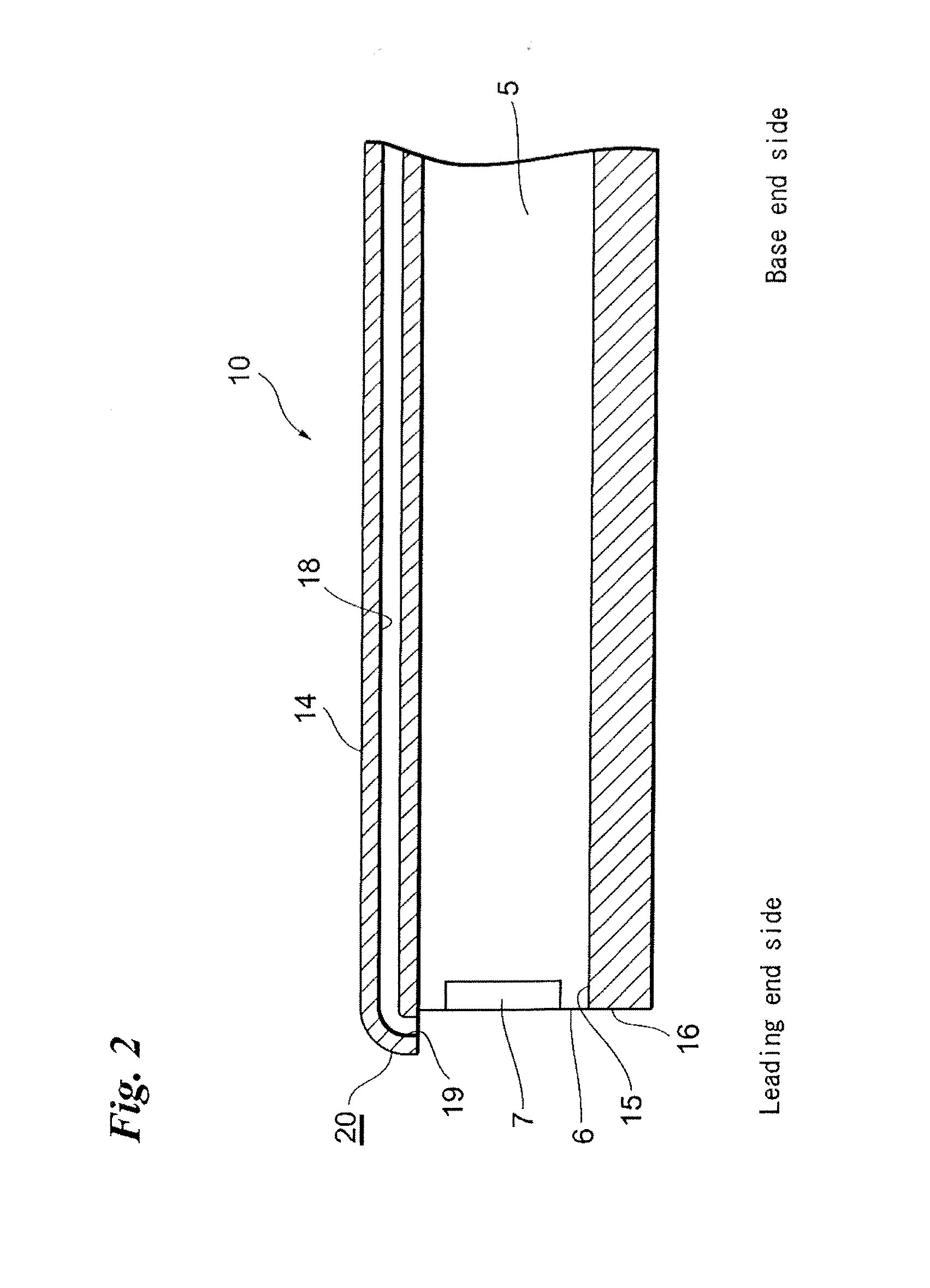
[0009]In accordance with the first aspect above, the ejection port is formed in the leading end portion of the rigid-endoscope oversheath to eject therefrom fluid flowing through the flow path from the base end toward the leading end along the longitudinal shaft of the rigid-endoscope oversheath. A peripheral portion of the ejection port is at least partially formed with an elastic member deformable by the fluid flowing through the flow path. Since the peripheral portion of the ejection port is at least partially formed with the elastic member, the ejection port is deformed elastically, when fluid is ejected from the ejection port, according to the flow rate of the fluid. The elastic deformation of the elastic member results in an increase in the size of the ejection port. Since the ejection port is deformed according to the amount of ejection of the fluid, the direction of ejection of the fluid from the ejection port also changes. That is, the direction of ejection of the fluid can be controlled according to the flow rate of the fluid flowing through the flow path. For example, when the flow rate is low, the ejection port is not deformed to remain narrower, so that the fluid is ejected at higher speed. This allows the fluid with even a lower flow rate to be ejected far away in the direction in which the ejection port is opened. When the flow rate is high, the ejection port is deformed to be widened, so that the fluid can be ejected widely. In particular, since this aspect includes no adjustment of the temperature of the fluid, there is no need to raise and keep the temperature of the cleaning solution and / or gas flowing through the flow path higher than that of the body, which allows the direction of ejection of the fluid to be adjusted relatively easily.
[0021]In accordance with the second aspect above, the ejection port includes the movable portion displaceable with respect to the rigid-endoscope oversheath and the non-movable portion fixed with respect to the rigid-endoscope oversheath, and the movable portion is urged such that the first area of the ejection port when fluid is ejected from the ejection port is greater than the second area of the ejection port when no fluid is ejected from the ejection port. Since the ejection port is widened according to the amount of ejection of the fluid, the direction of ejection of the fluid from the ejection port also changes. That is, also in this second aspect, the direction of ejection of the fluid can be controlled according to the flow rate of the fluid flowing through the flow path.

Problems solved by technology

The elastic deformation of the elastic member results in an increase in the size of the ejection port.

Method used


Image

  • Rigid-endoscope oversheath
  • Rigid-endoscope oversheath
  • Rigid-endoscope oversheath

Examples


Embodiment Construction

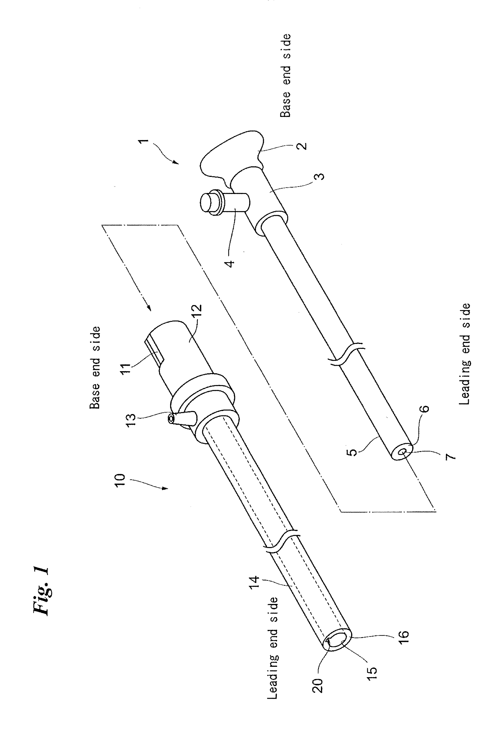
[0039]FIG. 1 is a perspective view showing a rigid endoscope 1 and a rigid-endoscope oversheath 10 to cover the rigid endoscope 1, according to a preferred embodiment of the present invention.

[0040]The rigid endoscope 1 includes a relatively long cylindrical insertion portion 5 to be inserted into a body cavity. At the base end of the insertion portion 5 is formed an operational portion (gripper) 3. At the rear end (base end) of the operational portion 3 is formed an eye piece 2. On the side surface of the operational portion 3 is formed a light-guide base 4 in a radially standing manner. The light-guide base 4 is intended to receive a light guide (not shown) for illuminating a test object. At the leading end 6 of the insertion portion 5 is attached a cover glass 7.

[0041]The rigid-endoscope oversheath 10 is formed with a circular tubular insertion portion 14 to cover the insertion portion 5 of the rigid endoscope 1. Inside the insertion portion 14 is formed an insertion path 15 for ...


PUM


Abstract

A cleaning nozzle is formed at a leading end face of a rigid-endoscope oversheath to cover a rigid endoscope. The cleaning nozzle is connected with a flow path formed in the oversheath so that fluid flowing through the flow path is ejected from an ejection port. The side surfaces of the cleaning nozzle are composed of a relatively hard material, while the upper surface is composed of a relatively soft material. When the flow rate of the fluid ejected from the ejection port is high, the upper surface of the ejection port is widened upward and thereby the direction of ejection of the fluid also changes. The direction of ejection of the fluid can thus be changed by controlling the flow rate.

Description

BACKGROUND OF THE INVENTION[0001]1. Field of the Invention[0002]The present invention relates to a rigid-endoscope oversheath.[0003]2. Description of the Related Art[0004]During surgery and / or treatment within body cavities using a rigid endoscope, the glass face at the leading end of the rigid endoscope may get dirty with splattered blood and / or body fluid. Further, using an electrosurgical knife or the like may generate smoke and / or mist, which in turn may attach to the glass face of the rigid endoscope. When the leading end face of the rigid endoscope gets dirty, the rigid endoscope is taken out of the body cavity and extraneous matters on the leading end face of the rigid endoscope are removed with, for example, gauze to ensure the scope and visibility.[0005]There have been proposed some techniques of covering an endoscope with an endoscope cleaning sheath to clean the leading end face of the endoscope (see Japanese Unexamined Patent Application Publication No. Hei 8-173370, for...

Claims


Application Information

Patent Timeline
IPC IPC(8): A61B1/12
CPCA61B1/00091A61B1/126A61B1/00135
Inventor YOSHIDA, KOJITORISAWA, NOBUYUKI
Owner FUJIFILM CORP
Learn More