Group-III Nitride Crystal Composite
a nitride crystal and composite technology, applied in the direction of crystal growth process, polycrystalline material growth, transportation and packaging, etc., can solve the problems of n gan crystal of superior crystallinity that have not been obtainable, and achieve superior crystallinity and light-emission efficiency. , the effect of superior crystallinity
- Summary
- Abstract
- Description
- Claims
- Application Information
AI Technical Summary
Benefits of technology
Problems solved by technology
Method used
Image
Examples
embodiment 1
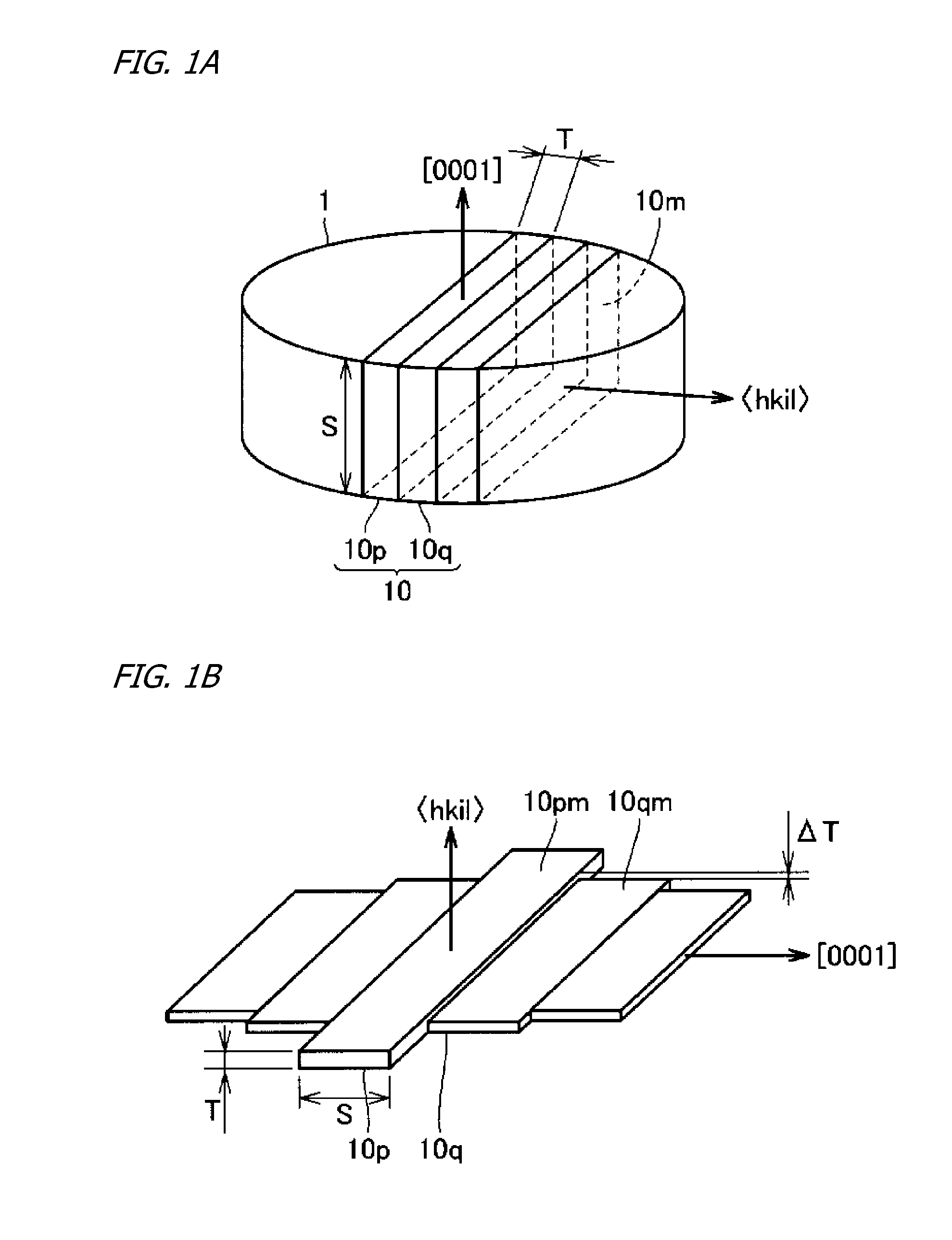
[0100]To begin with, referring to FIG. 3A, the (0001) face and (000-1) face—the two major surfaces—of GaN bulk crystal (III-nitride bulk crystal 1) were ground and polished to bring the roughness average Ra of either major surface to 5 nm. Here measurement of the surface roughness average Ra was carried out by AFM.
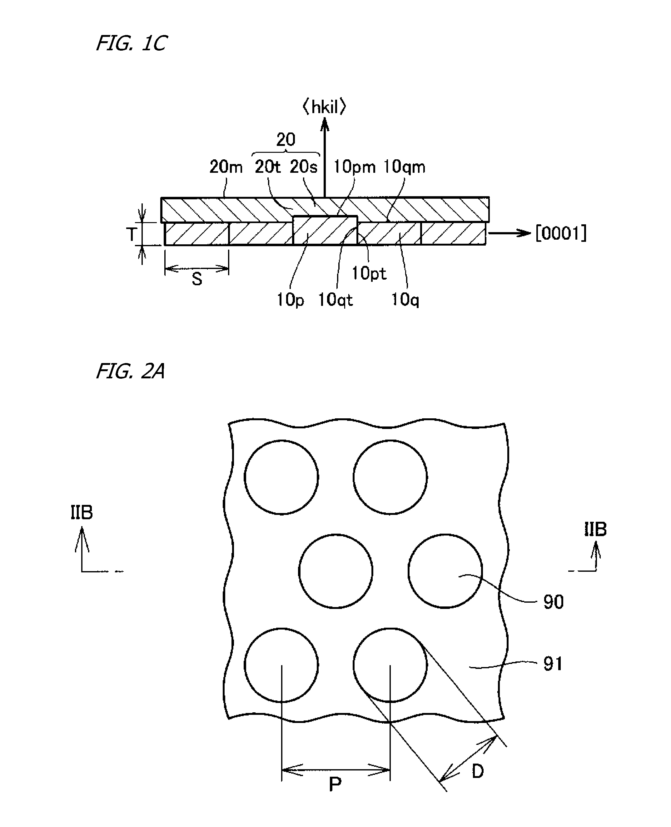
[0101]Next, referring to FIG. 3A, the GaN bulk crystal (III-nitride bulk crystal 1) whose roughness average Ra on either of its major surfaces had been made 5 nm was sawed along a plurality of planes perpendicular to a direction to slice off a plurality of GaN crystal substrates (III-nitride crystal substrates 10p, 10q) whose width S was 3 mm, length L was 20 to 50 mm, and thickness T was 1 mm, having {1-100} major surfaces. Subsequently, the not-ground and not-polished four sides of each sliced-off GaN crystal substrate were ground and polished, to bring the roughness average Ra of the four surfaces to 5 nm. A plurality of GaN crystal substrates whose roughness average R...
embodiment 2
[0107]Reference is again made to FIG. 3A: Apart from grinding and polishing the (0001) face and (000-1) face—the two major surfaces—of GaN bulk crystal (III-nitride bulk crystal 1) to bring the roughness average Ra of either major surface to 50 nm, in the same manner as in Embodiment 1, plural GaN crystal substrates (III-nitride crystal substrates 10p, 10q) were sliced off, and the not-ground and not-polished four sides of each GaN crystal substrate were ground and polished, to bring the roughness average Ra of the four surfaces to 5 nm. Among the plurality of GaN crystal substrates were GaN crystal substrates whose major-surface plane orientation did not coincide perfectly with {1-100}, but the plane orientation of the major surface of such GaN crystal substrates in all cases was misoriented by 5° or less with respect to {1-100}.
[0108]Next, referring to FIG. 3B, the plural GaN crystal substrates (III-nitride crystal substrates 10p, 10q) were situated in the same manner as in Embodi...
embodiment 3
[0113]To begin with, referring to FIG. 5A, the (0001) face and (000-1) face—the two major surfaces—of GaN bulk crystal (III-nitride bulk crystal 1) were ground and polished to bring the roughness average Ra of either major surface to 5 nm.
[0114]Next, again referring to FIG. 5A: The GaN bulk crystal (III-nitride bulk crystal 1) whose roughness average Ra on either of its major surfaces had been made 5 nm was sawed along a plurality of planes perpendicular to a direction to slice off a plurality of GaN crystal substrates (III-nitride crystal substrates 10p, 10q) whose width S was 3 mm, length L was 20 to 50 mm, and thickness T was 1 mm, having {11-20} major surfaces. Subsequently, the not-ground and not-polished four sides of each sliced-off GaN crystal substrate were ground and polished, to bring the roughness average Ra of the four surfaces to 5 nm. A plurality of GaN crystal substrates whose roughness average Ra on the {11-20} major surfaces was 5 nm was thus obtained. Among these...
PUM
| Property | Measurement | Unit |
|---|---|---|
| height ΔT | aaaaa | aaaaa |
| height ΔT | aaaaa | aaaaa |
| height ΔT | aaaaa | aaaaa |
Abstract
Description
Claims
Application Information
 - R&D
- Intellectual Property
- Life Sciences
- Materials
- Tech Scout
- Unparalleled Data Quality
- Higher Quality Content
- 60% Fewer Hallucinations
Browse by: Latest US Patents, China's latest patents, Technical Efficacy Thesaurus, Application Domain, Technology Topic, Popular Technical Reports.
© 2025 PatSnap. All rights reserved.Legal|Privacy policy|Modern Slavery Act Transparency Statement|Sitemap|About US| Contact US: help@patsnap.com


