
Multi-level modulation system and method

a multi-level modulation and multi-level technology, applied in the field of transmitters, can solve problems such as disadvantages and technical problems of single frequency networks, and achieve the effects of low signal to noise ratio, effective and efficient way of inserting local content, and easy recovery

Inactive Publication Date: 2012-12-13
SONY CORP
View PDF5 Cites 63 Cited by
  • Summary
  • Abstract
  • Description
  • Claims
  • Application Information

AI Technical Summary

Benefits of technology

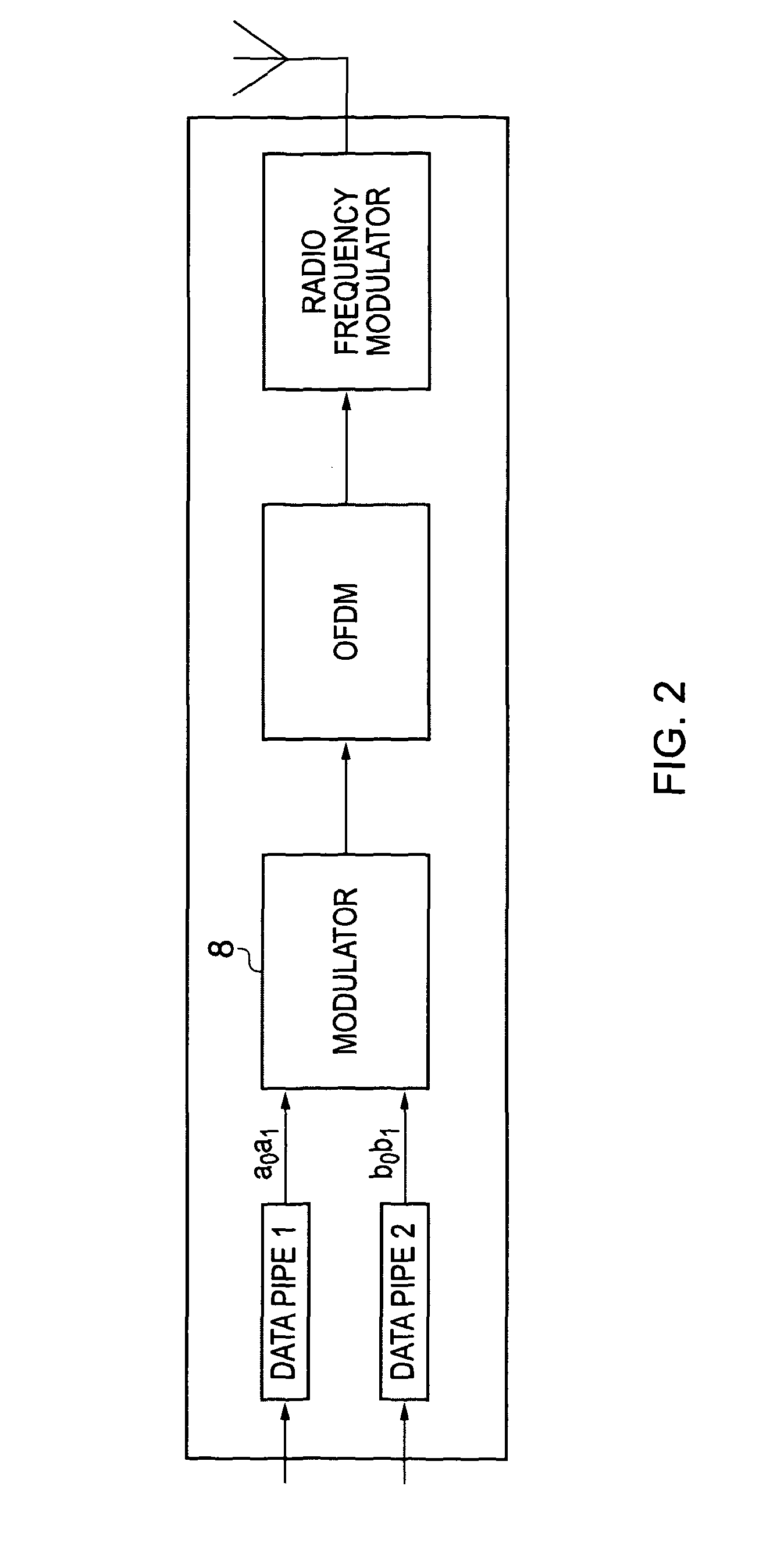
[0016]the first modulation scheme is a lower order modulation scheme providing first modulation symbols with values from a smaller number of constellation points in the complex plane than the second modulation scheme which is a higher order modulation scheme, the second modulation scheme providing second modulation symbols with values which are disposed in the complex plane about corresponding values of the first modulation scheme, with the effect that detection of one of the second modulation symbols of the second modulation scheme will provide data symbols from the local service insertion pipe and / or the first data pipe and allow the detection of first modulation symbols from the first modulation scheme providing data symbols from the first data pipe, in the presence of modulation symbols from the second modulation scheme, thereby providing the modulator with a plurality of modulation layers.
[0018]According to example embodiments of the present invention, a communication system is arranged such that one or more base stations from a plurality of base stations which form a communications network are selected to transmit OFDM symbols which have sub-carriers modulated in accordance with the second modulation scheme. Thus, the second modulation scheme is used to convey data symbols from both the first data pipe and the local service insertion pipe. Because of the arrangement of the second modulation scheme with respect to the first modulation scheme, the data symbols from the first data pipe may be received even when transmitted on the same radio frequency carrier, because detection of a constellation point from the first modulation scheme will require a lower signal to noise ratio than the second modulation scheme. This is because the first modulation scheme forms a sub-set of constellation points in the complex plane of the second modulation scheme, which can be thought of as a more coarse version of the second modulation scheme, so that differentiation between constellation points of the first modulation symbols in the complex plane allows the data from the first data pipe to be more easily recovered. Furthermore, because other base stations may not be communicating the local service insertion pipe data, receivers, within the geographical area in which these other base stations are disposed, will still be able to detect the data from the first data pipe. This is because OFDM signals transmitted from a neighbouring base station on the common radio frequency carrier using the second modulation scheme will simply appear as noise with respect to a detector detecting OFDM symbols according to the first modulation scheme. Thus an effective and efficient way of inserting local content in a single frequency network is provided.
[0019]In some examples, the transmitter may include a scheduler for forming the modulated sub-carrier signals into the OFDM symbols and a framing unit which arranges the OFDM symbols for transmission according to a time division multiplexed frame. Furthermore, the scheduler and the framing unit are arranged to transmit OFDM symbols which are carrying data symbols from both the first data pipe and the local service insertion pipe using the second modulation scheme in some time division multiplexed frames and not others. More particularly, in other examples, the base stations of the communications network maybe formed into clusters, each cluster including a predetermined number of the base stations, each base station in the cluster being assigned to one of a corresponding number of time division multiplexed frames, and the transmitter of the base station is arranged to transmit the OFDM symbols which are carrying data symbols from both the first data pipe and the local service insertion pipe using the second modulation scheme in the time division multiplexed frame which has been assigned to that base station and not others. As a result an amount of “interference” caused by transmitting OFDM symbols using the second modulation scheme on the common radio frequency carrier to a receiver which is detecting and recovering the data symbols from OFDM symbols modulated using the first modulation scheme will be reduced in proportion to the number of base stations in each cluster. The word “interference” is used here in the sense that the OFDM symbols with sub-carriers modulated in accordance with the second modulation scheme will increase the noise level of a receiver detecting data symbols carried by OFDM symbols with sub-carriers modulated in accordance with the first modulation scheme, because as explained above a property of a layered modulation arrangement will be to increase noise to a receiver.

Problems solved by technology

Whilst a single frequency network has advantages in terms of operation and improved integrity of the communicated data, it also suffers a disadvantage if data local to a part of the geographical area is required to be communicated.
However, providing an arrangement to insert data locally in a single frequency network presents a technical problem.

Method used


Image

  • Multi-level modulation system and method
  • Multi-level modulation system and method
  • Multi-level modulation system and method

Examples


Embodiment Construction

[0047]As set out above embodiments of the present invention seek to provide, in one application, an arrangement in which local content can be transmitted within a single frequency network whilst allowing other parts of the network still to receive a primary broadcast signal. One example illustration is where local content is required to be broadcast contemporaneously with a national broadcast television programme.

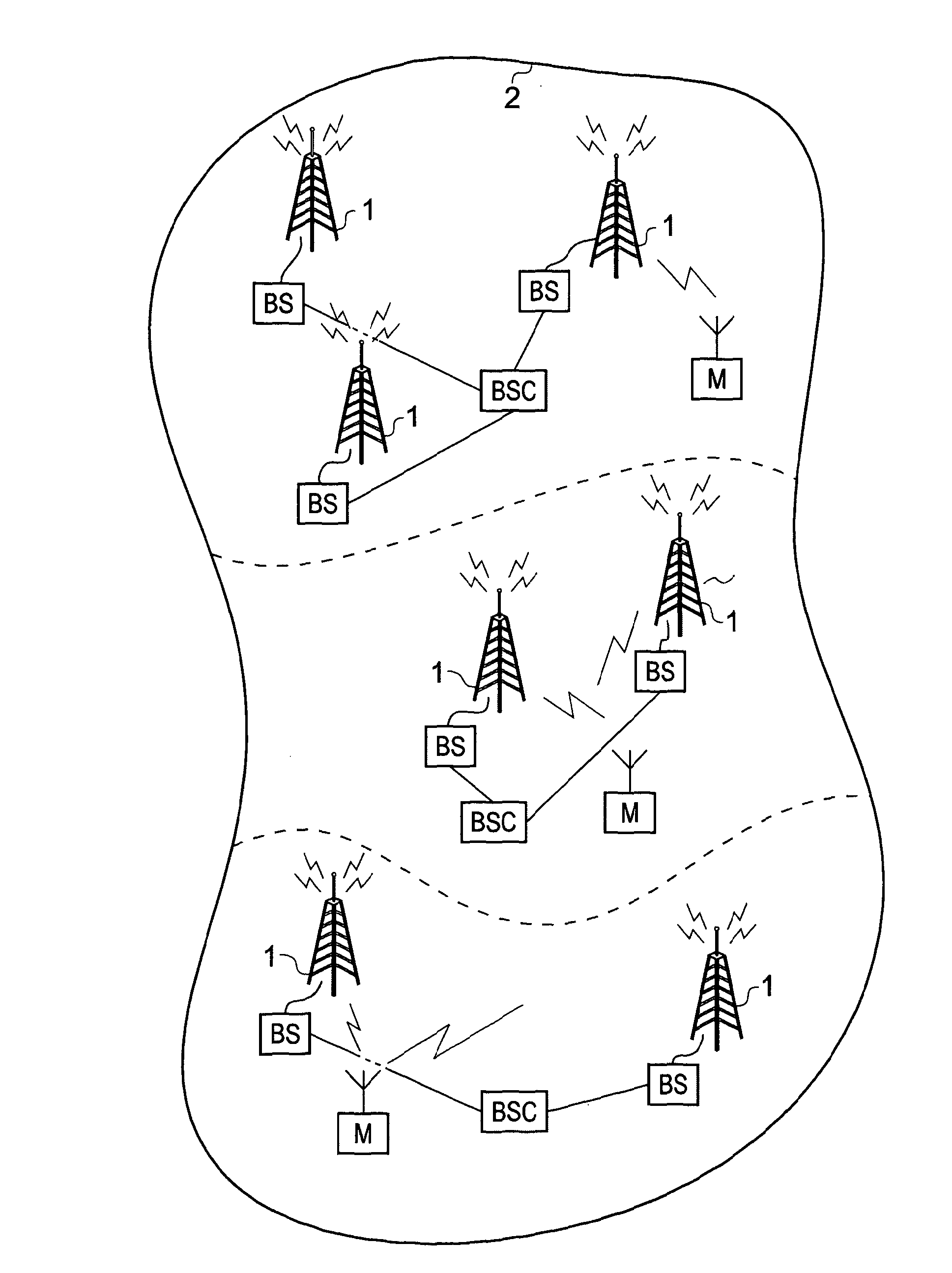
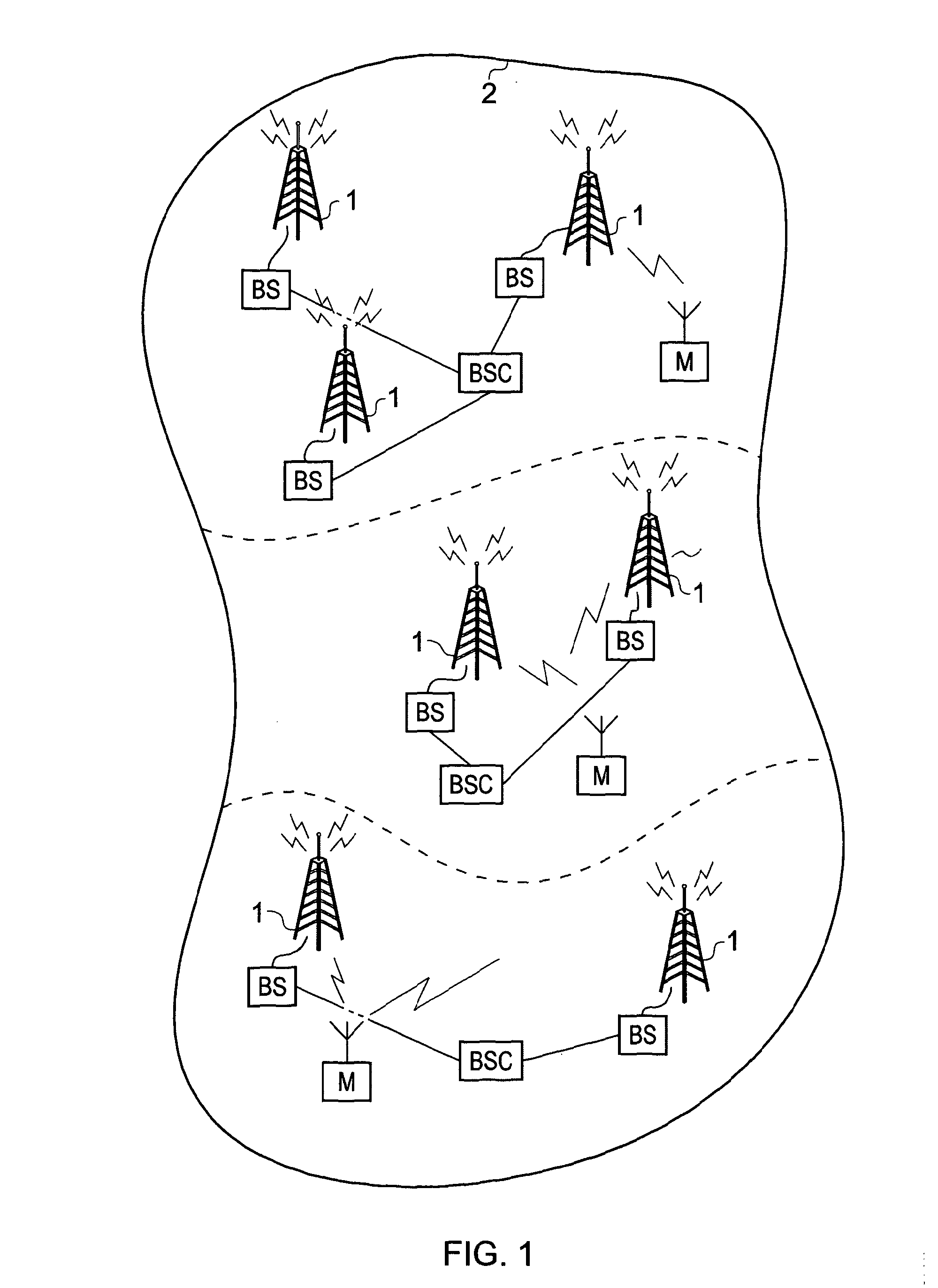
[0048]FIG. 1 provides an example illustration of a network of base stations BS which are transmitting, via transmit antennas 1, a signal in accordance with a commonly modulated OFDM signal. The base stations BS are disposed throughout a geographical area within a boundary 2, which may be, in one example, a national boundary. As explained above in a single frequency network configuration the base stations BS are all broadcasting the same OFDM signal at the same time on the same frequency. Mobile devices M may receive the OFDM signal from any of the base stations. More partic...


PUM


Abstract

A transmitter communicating data using Orthogonal Frequency Division Multiplexed (OFDM) symbols including plural sub-carrier symbols in the frequency domain for modulating with data to be carried. The transmitter includes a modulator to receive data symbols from a first data pipe according to a first communications channel, to receive data symbols from a local service insertion data pipe according to a local communications channel, and to modulate the sub-carrier signals of the OFDM symbols with either the data symbols from the first data pipe or from both the first data pipe and the local service insertion pipe; modulation from the first data pipe maps the data symbols is according to a first modulation scheme, and modulation from the first data pipe and the local service insertion pipe maps the data symbols is according to a second modulation scheme.

Description

FIELD OF INVENTION[0001]The present invention relates to transmitters for transmitting data via Orthogonal Frequency Division Multiplexed (OFDM) symbols in which the data is provided from a plurality of different data pipes.[0002]Embodiments of the present invention find application in receiving data communicated using OFDM symbols which are transmitted using communication systems which comprise a plurality of base stations disposed throughout a geographical area. In some embodiments the communication system is arranged to broadcast video, audio or data.BACKGROUND OF THE INVENTION[0003]Orthogonal Frequency Division Multiplexing (OFDM) is a modulation technique which has found much favour in communication systems, such as for example diose designed to operate in accordance with the first and second generation Digital Video Broadcasting terrestrial standards (DVB-T / T2) and is also being proposed for fourth generation mobile communication systems which are also known as Long Term Evolu...

Claims


Application Information

Patent Timeline
IPC IPC(8): H04L27/28H04L27/06H04L27/00
CPCH04L27/3488H04L5/0001H04L27/2604H04L27/3472H04L27/345H04L27/2626H04L5/0007H04L5/023H04L27/0008
Inventor ATUNGSIRI, SAMUEL ASANBENGSTADELMEIER, LOTHARMUHAMMAD, SVENROBERT, JORGOKEHIE, OBIOMA CHIEDOZIE DONALDTAYLOR, MATTHEW PAUL ATHOLZOELLNER, JAN
Owner SONY CORP
Learn More