
Multi-frequency synchronous modified large range high precision fast laser ranging method and apparatus

A technology of synchronous modulation and laser ranging, which is used in measurement devices, re-radiation of electromagnetic waves, radio wave measurement systems, etc., and can solve problems such as target position changes, slow measurement speed, and measurement errors.

Inactive Publication Date: 2006-08-30
HARBIN INST OF TECH
View PDF3 Cites 56 Cited by
  • Summary
  • Abstract
  • Description
  • Claims
  • Application Information

AI Technical Summary

Problems solved by technology

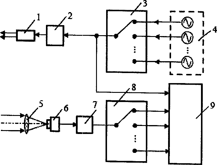
The shortcomings of this method are mainly manifested in the following two points: First, the measurement speed is slow. During the measurement, it is necessary to measure the target at multiple frequencies, and then obtain the final measurement result through data fusion. The total ranging time varies with the number of measuring ruler frequencies Second, when measuring the moving target, the position of the target may change during the multi-frequency measurement process, resulting in measurement errors

Method used


Image

  • Multi-frequency synchronous modified large range high precision fast laser ranging method and apparatus
  • Multi-frequency synchronous modified large range high precision fast laser ranging method and apparatus
  • Multi-frequency synchronous modified large range high precision fast laser ranging method and apparatus

Examples


Embodiment 1

[0056] Dual frequency synchronous modulation phase laser distance measuring device

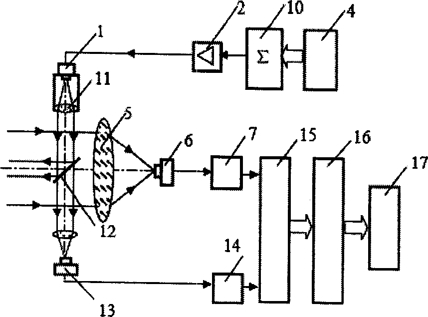
[0057] Such as Figure 6As shown, the device is mainly composed of a semiconductor laser 23, a laser emitting lens 11, a beam splitter 12, a converging lens 29, a reference light photodetector (PIN) 13, a laser receiving lens 5, a measuring light photodetector (APD) 6, and a measurement Photoelectric conversion circuit 7, reference light photoelectric conversion circuit 14, laser power modulation drive unit 2, dual-frequency signal characteristic pre-compensation weighted sum processing unit 24, signal generation units 25 and 26, high-frequency band-pass filter units 31 and 34, Low-frequency band-pass filtering units 33 and 36, high-frequency mixing units 37 and 39, fine local oscillator and coarse local oscillator generating units 32 and 35, low-frequency mixing units 38 and 40, low-pass filtering units 41 and 42, low-pass filtering Units 43 and 44, phase difference measurement units 45 and ...

Embodiment 2

[0065] Three-frequency synchronous modulation phase laser distance measuring device

[0066] Such as Figure 6 As shown, in this example, on the basis of the dual-frequency synchronously modulated phase-type laser ranging device, a modulation signal is added to the transmitting unit, that is, the frequency of the coarse measuring scale f 2 , f 2 Taking 750Hz, the signal is also realized by direct digital synthesis technology; correspondingly, a band-pass filter frequency selection phase measurement circuit is added in the receiving unit, in which the center frequency of the band-pass filter is 750Hz, and the -3dB bandwidth is 100Hz; the phase difference measurement unit is adjusted It is a three-frequency synchronous digital phase measurement. Other units and working principles of this example are the same as Example 1. The theoretical range of the distance measuring device is 200Km.


PUM


Abstract

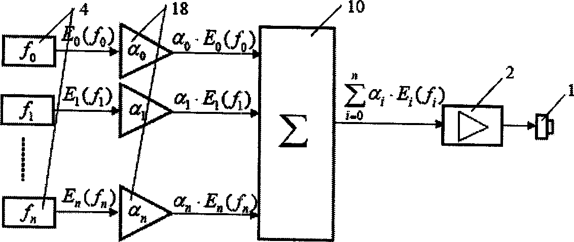
The invention relates to a wide range high accuracy fast laser distance measuring method and device based on multiple frequency synchronous condenser. The multiple frequency modulating signals are taken characteristic pre-compensation weight summarizing at laser emitting unit. After compounding, the laser power is modulated to take distance measuring. Synchronous band pass filter frequency selection and phase determination method is used to taken signal process. The method could gain the distance measuring result of distance measuring frequency in multiple frequency modulating distance measuring, and gain the final distance result. The distance measuring speed and real time is ensured. It also avoids measuring error coursed by the location movement of the target.'

Description

technical field [0001] The invention belongs to the technical field of laser ranging, in particular to a large-range, high-precision and fast laser ranging method and device based on multi-frequency synchronous modulation. Background technique [0002] Laser ranging is a comprehensive technology that integrates various technologies such as optics, laser, optoelectronics and integrated electronics. Semiconductor laser ranging devices are widely used in military, aerospace, robot vision, industrial automatic production lines and other fields due to their advantages of non-contact, high precision, small size, low cost, and long service life. For absolute distance measurement, the commonly used laser ranging methods are pulse method and phase method. The pulse method has the advantages of wide measurement range, fast speed, suitable for non-cooperative targets, etc., but its measurement accuracy is low. The distance measuring device using a pulsed semiconductor laser can measu...

Claims


Application Information

Patent Timeline
IPC IPC(8): G01S17/08
Inventor 谭久彬刘思远侯滨可刘俭
Owner HARBIN INST OF TECH
Learn More