
Component Supporting Device

a technology of supporting device and component, which is applied in the direction of electrical equipment, manufacturing tools, electric discharge tubes, etc., can solve the problems of product damage caused by static electricity, electrostatic damage (esd) and electrostatic attraction (esa), lattice damage, and transistor breakdown, etc., to achieve rapid removal of static electricity, uniform effect, efficient

Inactive Publication Date: 2012-12-13
SHENZHEN CHINA STAR OPTOELECTRONICS TECH CO LTD
View PDF3 Cites 10 Cited by
  • Summary
  • Abstract
  • Description
  • Claims
  • Application Information

AI Technical Summary

Benefits of technology

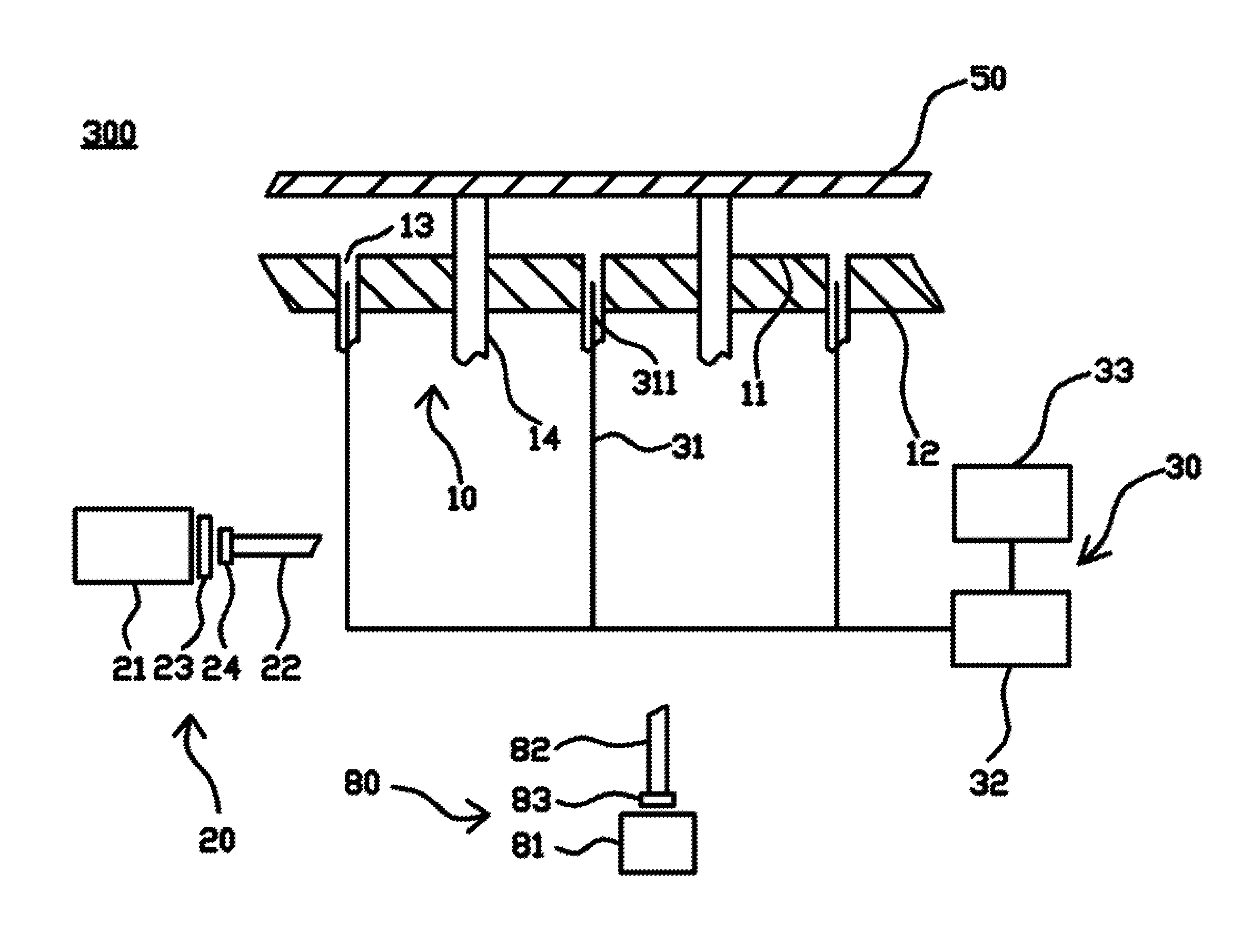
[0010]A primary object of the present invention is to provide a component supporting device, which comprises a platform, a vacuum system, a gas supply system and a discharger system. The platform has a supporting surface and at least one through hole, and the through hole is formed between the supporting surface and the bottom surface; the vacuum system provides a vacuum suction to the through hole; the gas supply system is used to output at least one type of gas to the through hole; the discharger system ionizes the gas into an ion fluid; wherein the through hole is used to provide the vacuum suction for supporting and sucking a component, or to provide the ion fluid when releasing the vacuum suction for removing static electricity on a surface of the component. Thus, the component supporting device can more efficiently, uniformly and rapidly remove the static electricity on the surface of the component.
[0011]A secondary object of the present invention is to provide a component supporting device, which comprises a platform, a vacuum system, a gas supply system and a discharger system. The platform has a supporting surface, at least one through hole and a plurality of pins. The through hole is formed on the supporting surface, and the pins are stored in the platform or extended out from the supporting surface; the vacuum system provides a vacuum suction to the through hole; the gas supply system outputs at least one type of gas by a pressure; and the discharger system has at least one discharge tube and a power supply. The discharge tube discharges the gas to be ionized into an ion wind; a power supply is used to provide an electric signal to the discharge tube, wherein the through hole is used to provide the vacuum suction for supporting and sucking a component, or to provide the ion fluid when releasing the vacuum suction for removing static electricity on a surface of the component. The discharger system continuously monitors for decreasing an ionization degree of the gas when the static electricity on the surface of the component is continuously reduced, so as to ensure to stop generating the ion fluid after the static electricity on the surface of the component is removed. Thus, it will not cause redundant ion fluid to be accumulated on the component.
[0012]A third object of the present invention is to provide a component supporting device, wherein the gas supply system comprises a gas supply, a conduit and a sieve. The conduit is connected to the supporting surface and the through hole, and the sieve disposed between the gas supply and the through hole is used to filter the gas. It not only can help the gas which passed through the sieve to become clearer for generating purer ion fluid, but also can filter dusts or impurities outputted from the gas supply. Thus, it is helpful to ensure that there will be no electrostatic particles or dusts remained on the surface of the component.
[0024]Comparing to the existing technology, the component supporting device in the present invention can more efficiently, uniformly and rapidly remove the static electricity on the surface of the components, and also can continuously monitor at the same time for decreasing an ionization degree of the gas when the static electricity on the surface of the components is continuously reduced, so as to ensure to stop generating the ion fluid after the static electricity on the surface of the components is removed, and then to stop providing the ion fluid. Thus, it will not cause redundant ion fluid accumulated on the components and can ensure that there will be no electrostatic particles or dusts remained on the components, and thus a yield of the product thereof can be achieved.

Problems solved by technology

During processes of making liquid crystal displays (LCDs), plasma display panels (PDPs) and semiconductors, there are frequently a plurality of static electricity phenomena accompanied with the processes, result in damages or defects of product.
The main harm of products caused by the static electricity is electro-static damages (ESD) and electro-static attractions (ESA).
The electro static damage means that static electricity discharges to cause lattice damages and transistor breakdowns, and the electro static attraction means that the static electricity is used to the attachment of fine dusts.
The two electro-static problems generally happen at the same time and result synergistic damages to products, so that a yield of products is sharply dropped, and thus the manufacture cost of products are increased.
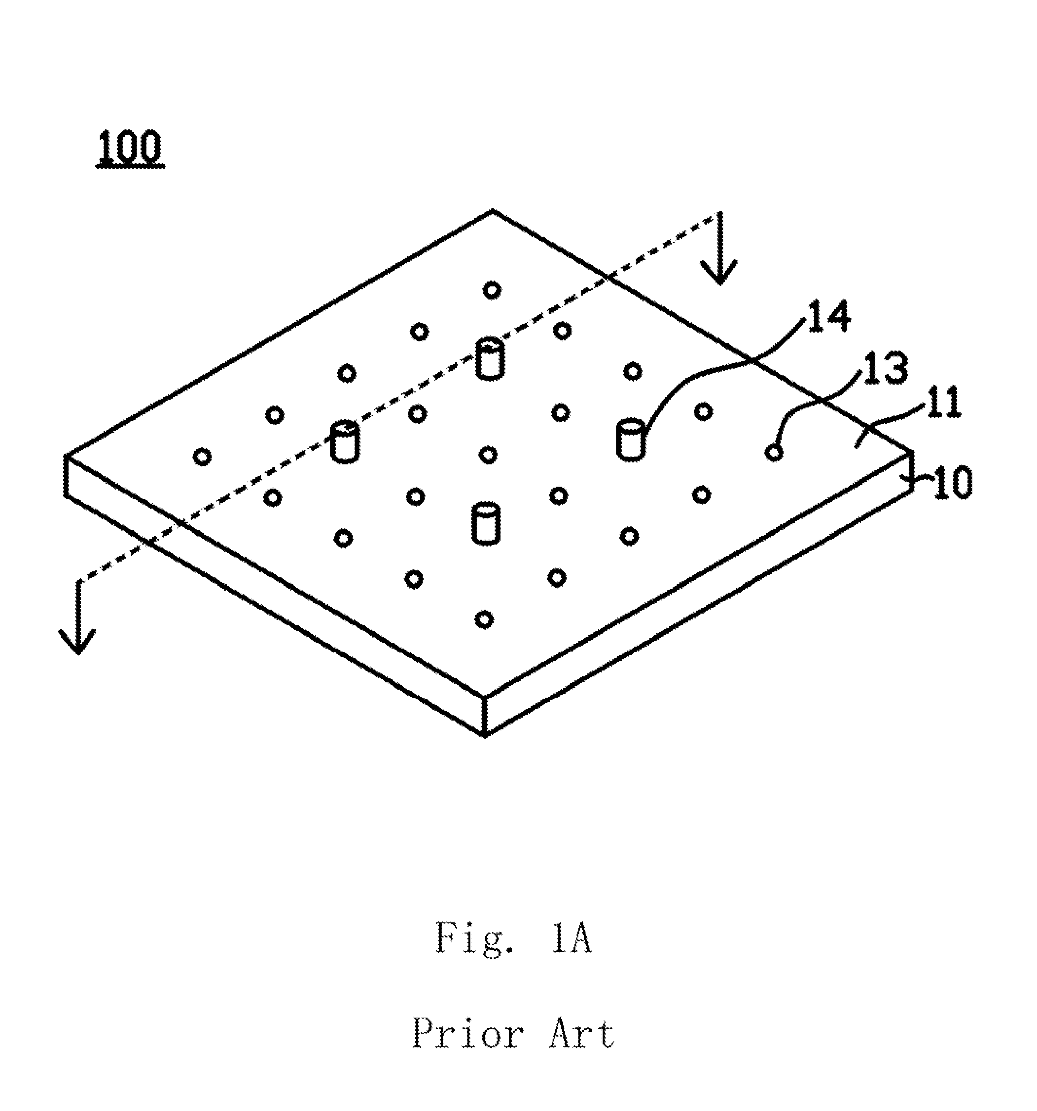
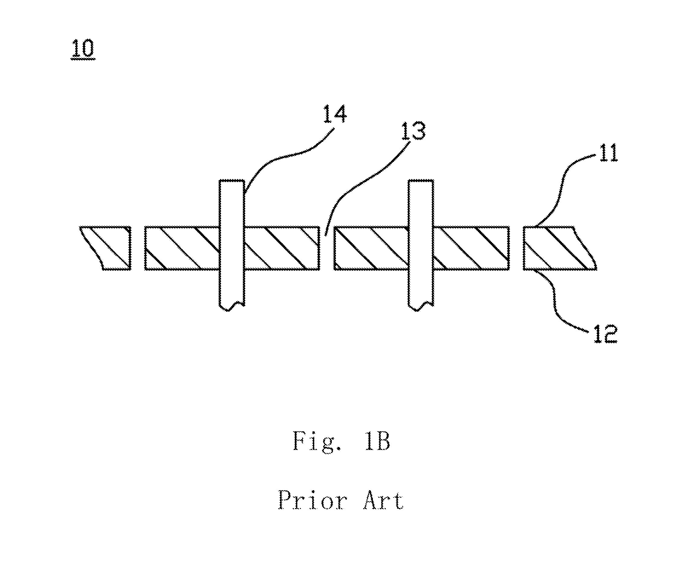
However, as to the considerable static electricity generated due to the suddenly separation of the substrate 40 from the platform 10, the ion wind of the ionizing fan bar 60 cannot reach the bottom surface of the substrate 40 and cannot efficiently rapidly remove the static electricity.
As to the X-ray device 70, there are disadvantages of high apparatus prices, harmful risk of X-rays to people, ionic disequilibrium of the surrounding environment easily occurred after removing the static electricity and so on, it is hard to be widely used in electronic industries.

Method used


Image

  • Component Supporting Device
  • Component Supporting Device
  • Component Supporting Device

Examples


Embodiment Construction

[0031]The foregoing objects, features and advantages adopted by the present invention can be best understood by referring to the following detailed description of the preferred embodiments and the accompanying drawings. Furthermore, the directional terms described in the present invention, such as upper, lower, front, rear, left, right, inner, outer, side and etc., are only directions referring to the accompanying drawings, so that the used directional terms are used to describe and understand the present invention, but the present invention is not limited thereto.

[0032]The present invention is to provide a component supporting device which is mainly applied to the field of insulator processes, and more particularly to the field of processes for semiconductor or optoelectronic products. It is mainly used to remove static electricity on a surface of the component that is generated at an instant of separating a component from a platform, so as to prevent the component from being damag...


PUM


Abstract

The present invention provides a component supporting device which has: a platform, a vacuum system, a gas supply system and a discharger system. The platform has a supporting surface, a bottom surface and at least one through hole, and the through hole passes through the supporting surface and the bottom surface. The vacuum system provides a vacuum suction to the through hole. The gas supply system is used to output at least one type of gas to the through hole. The discharger system ionizes the gas into an ion fluid. Thus, the through hole can be used to provide the vacuum suction for supporting and sucking a component, or to provide the ion fluid when releasing the vacuum suction for more efficiently, uniformly and rapidly removing static electricity on a surface of the component.

Description

FIELD OF THE INVENTION[0001]The present invention relates to a component supporting device, and more particularly to a component supporting device capable of removing static electricity on the surface thereof.BACKGROUND OF THE INVENTION[0002]During processes of making liquid crystal displays (LCDs), plasma display panels (PDPs) and semiconductors, there are frequently a plurality of static electricity phenomena accompanied with the processes, result in damages or defects of product. The main harm of products caused by the static electricity is electro-static damages (ESD) and electro-static attractions (ESA). The electro static damage means that static electricity discharges to cause lattice damages and transistor breakdowns, and the electro static attraction means that the static electricity is used to the attachment of fine dusts. The two electro-static problems generally happen at the same time and result synergistic damages to products, so that a yield of products is sharply dro...

Claims


Application Information

Patent Timeline
IPC IPC(8): B25B11/00
CPCB25B11/005H01J37/32935H01L21/67109
Inventor YAN, MAOCHENGSHIH, HSIANGYIN
Owner SHENZHEN CHINA STAR OPTOELECTRONICS TECH CO LTD
Learn More