Image scanning device, image forming device, and method for correcting pixel value for pixel corresponding to position of rod lens array joint
a technology of image scanning and image forming, which is applied in the direction of colour separation/tonal correction, instrumentation, photomechanical treatment, etc., can solve the problems of high cost, white or gray streaks, and gaps that can form
- Summary
- Abstract
- Description
- Claims
- Application Information
AI Technical Summary
Benefits of technology
Problems solved by technology
Method used
Image
Examples
second embodiment
[0111]Next, a process of setting a correction value for eliminating streaking according to a second embodiment will be described with reference to FIGS. 13 through 16. FIG. 13 is a conceptual graph describing correction for eliminating streaking. FIG. 14 is an illustrative view of one example of a correction scanning object for use in correction for eliminating streaking. FIG. 15 is a flow chart showing one example of a process of setting a correction value for eliminating streaking. FIG. 16 is a flow chart showing one example of a process of scanning a document using a correction value.
[0112]The second embodiment differs from the first embodiment in that a correction scanning object that is not solid black is scanned to set a correction value for eliminating streaking. With regard to other points, the second embodiment may be similar to the first embodiment, and will be considered to incorporate the description of the first embodiment, with any description or drawings of any parts ...
third embodiment
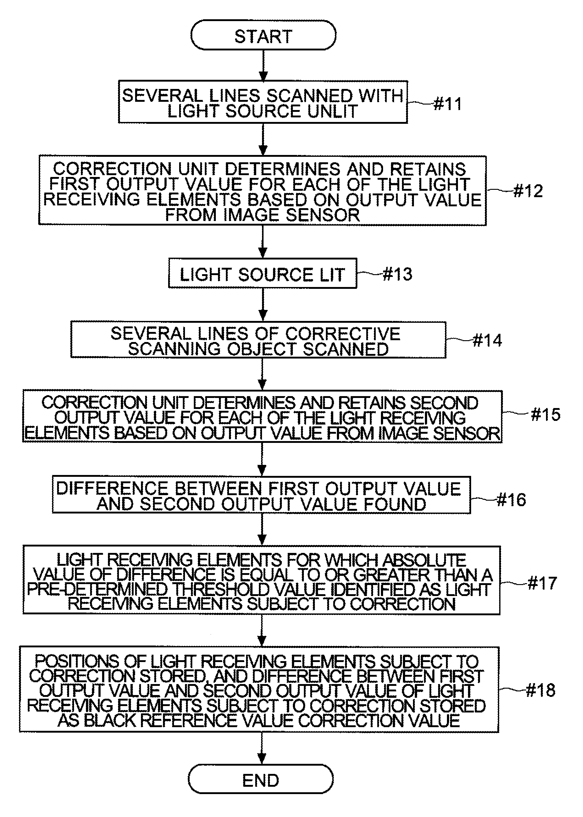
[0129]Next, a process of setting a correction value for eliminating streaking according to a third embodiment will be described with reference to FIG. 17. FIG. 17 is a flow chart showing one example of a process of setting a correction value for eliminating streaking.
[0130]This embodiment differs from the first and second embodiments in that light receiving elements 9 affected by ambient light entering through the joints between rod lens arrays 7 are identified simply by scanning a correction scanning object, and the black reference value of the light receiving elements 9 subject to correction identified by the correction unit 12 is corrected. With regard to other points, the third embodiment may be similar to the first and second embodiments, and will be considered to incorporate the description of the first and second embodiments, with any description or drawings of any parts in common being omitted.
[0131]The correction scanning object used in this embodiment is a solid-black corr...
fourth embodiment
[0142]Next, a process of setting a correction value for eliminating streaking according to a fourth embodiment will be described with reference to FIG. 18. FIG. 18 is a flow chart showing one example of a process of setting a correction value for eliminating streaking.
[0143]This embodiment, like the third embodiment, differs from the first and second embodiments in that light receiving elements 9 affected by ambient light entering through the joints between rod lens arrays 7 are identified simply by scanning a correction scanning object, and the black reference value of the light receiving elements 9 identified by the correction unit 12, which are considered light receiving elements 9 subject to correction, is corrected.
[0144]The fourth embodiment differs from the third embodiment in that a correction scanning object that is not solid black is scanned and a correction value for eliminating streaking is set. With regard to other points, the fourth embodiment may be similar to the thi...
PUM
 Abstract
Description
Claims
Application Information
 - R&D
- Intellectual Property
- Life Sciences
- Materials
- Tech Scout
- Unparalleled Data Quality
- Higher Quality Content
- 60% Fewer Hallucinations
Browse by: Latest US Patents, China's latest patents, Technical Efficacy Thesaurus, Application Domain, Technology Topic, Popular Technical Reports.
© 2025 PatSnap. All rights reserved.Legal|Privacy policy|Modern Slavery Act Transparency Statement|Sitemap|About US| Contact US: help@patsnap.com


