
Cord Switch for Controlling a LED Lamp

a technology of led lamps and cord switches, which is applied in the field of switches, can solve the problems of inconvenient mass production and assembly, and the end user's wire connection, and achieve the effect of simplifying the wire connection of the switch

Inactive Publication Date: 2012-12-06
OPENWISE IND
View PDF5 Cites 13 Cited by
  • Summary
  • Abstract
  • Description
  • Claims
  • Application Information

AI Technical Summary

Benefits of technology

[0004]In order to tackle the above mentioned technical problem, an object of the present invention is to provide a switch that uses pluggable connection terminals for plug-in connection, thereby simplifying considerably the wire connection of the switch.
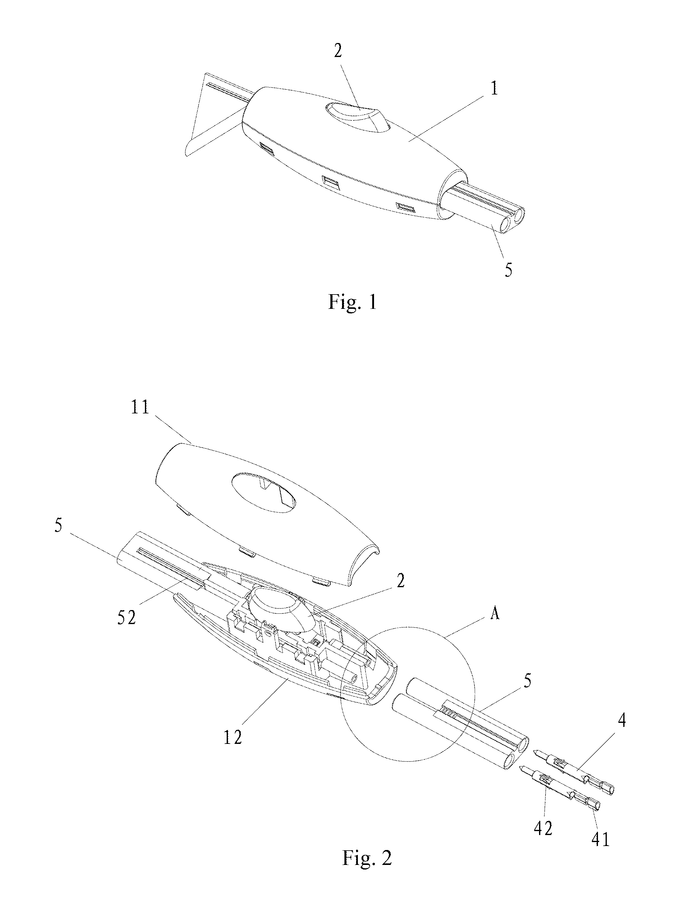
[0012]In a further preferred embodiment of the invention, a plurality of hook members projecting outward are provided on the underside of the upper casing portion and a plurality of slots matchable with the hook members are located in the lower casing portion; a plurality of inner notches which respectively engage with protrusions of the hook members are formed on an inner wall of the lower casing portion at upward positions which correspond to the slots. The inner notches are configured to provide the ease of guiding the hook members into the slots and to allow the simple and convenient assembly of the upper and lower casing portions through the hook members.
[0013]In a preferred embodiment of the invention, a partition for separating wires disposed in the lower casing portion is provided so as to avoid the contact between the two poles, effectively preventing the event of short circuit.
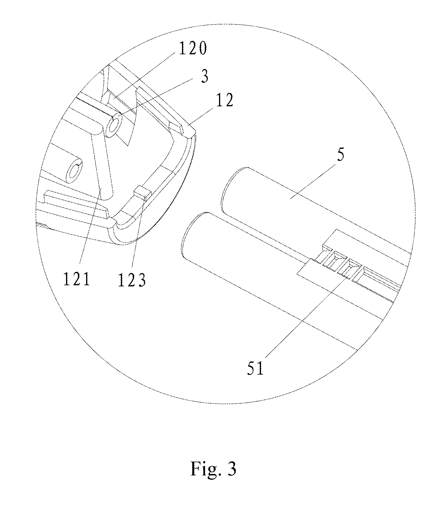
[0015]In a yet preferred embodiment of the invention, a barb portion for self-locking the housing is provided on an outer side wall of the housing between the two through holes, and a lock block is positioned respectively in the upper and lower casing portions to correspond to the barb portion. The lock block has a slant surface on the side from which the housing is inserted to provide the easy insertion, a vertical surface on the side from which the housing exits, allowing the barb portion to be locked firmly so that the housing is not detached easily.
[0016]In a further preferred embodiment of the invention, a guiding slot is provided on the housing at the opposite side to the barb portion, and a projecting block which matches with the guiding slot is positioned respectively in the upper and lower casing portions, where an opening for inserting the housing is located. By aligning the guiding slot with the projecting block, the connection between the housing and the casing is firm yet simple.
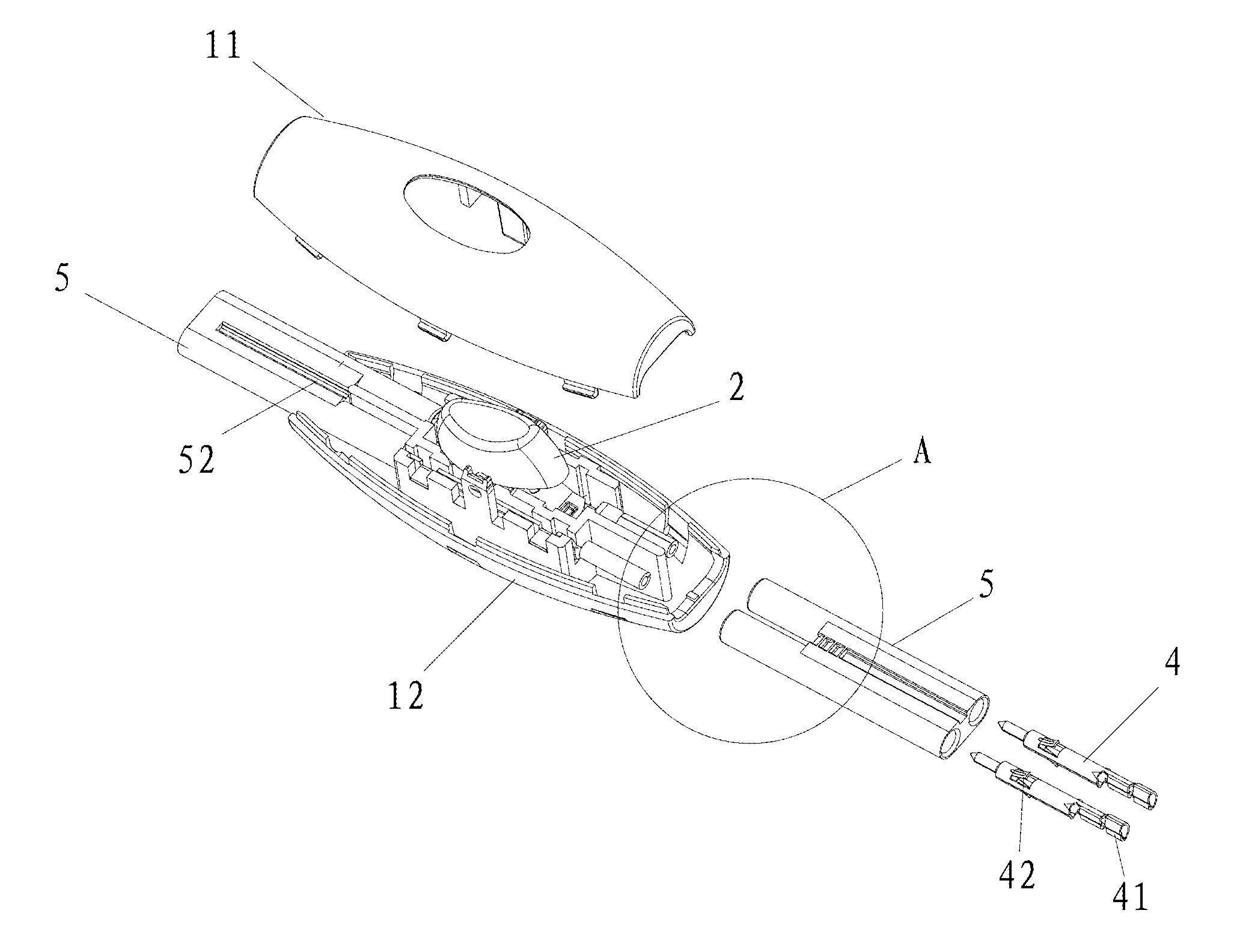
[0017]The advantages of this invention include the following. With the above-mentioned structures, the cord switch for controlling a LED lamp enables the wire connection by riveting the wires in the rivet portion at the rear end of the connection terminals, followed by inserting the connection terminals into the housing to form a connector which is then inserted into the casing. As such, there is no need to disassemble and reassemble the casing, or fasten the wires with bolts when connecting the wires. As a result, the efficiency of connecting and assembling can be increased effectively, making it possible for mass production and processing. In addition, the cord switch of this invention is characterized by appealing appearance and compact structure.

Problems solved by technology

This connection process involves a number of steps and is quite complicated, making it inconvenient for mass production and assembly and for the end users to perform the wire connections.

Method used


Image

  • Cord Switch for Controlling a LED Lamp
  • Cord Switch for Controlling a LED Lamp
  • Cord Switch for Controlling a LED Lamp

Examples


Embodiment Construction

[0026]Referring to FIGS. 1 to 7, there illustrate a cord switch for controlling a LED lamp constructed according to the invention, comprising a casing 1 which consists to of an upper casing portion 11 and a lower casing portion 12. The underside of the upper casing portion 11 has a plurality of hook members 110 projecting downward; and both sides of the lower casing portion 12 have a plurality of slots 120 which match with the hook members 110. On the inner wall of the lower casing portion 12 at upward positions which correspond to the slots 120, a plurality of inner notches 124 are provided which respectively engage with protrusions of the hook members 110. The inner notches 124 are configured to provide the ease of guiding the hook members 110 into the slots. The upper and lower casing portions 11 and 12 are assembled to form the casing 1 by interlocking the hook members 110 with the slots 120. In addition, a plurality of hook members projecting upward may be provided in the upper...


PUM


Abstract

The invention provides a cord switch for controlling a LED lamp, comprising a casing, a push button switch that consists of a push button and a conductive slice arranged in the casing, and connection terminals and housings for the connection terminals. Each connection terminal has a plug or a pin at its front end and a rivet portion at its rear end. The housing receives the connection terminals, forming a connector which is then inserted into the casing, with a part of the plug or the pin in close contact with the conductive slice. For this cord switch, the wire connection comprises the steps of riveting wires in the rivet portion at the rear end of the connection terminals, inserting the connection terminals into the housing to form a connector, and inserting the connector into the casing, without need to disassemble and reassemble the casing, or fasten the bolts.

Description

CROSS REFERENCE TO RELATED APPLICATIONS[0001]This utility patent application claims priority to Chinese patent application no. 201110149032.4 filed on Jun. 3, 2011, which is incorporated by reference herein.FIELD OF THE INVENTION[0002]This invention relates to a switch, and more particularly, to a cord switch for controlling a LED (Light Emitting Diode) lamp, which uses pluggable connection terminals to provide the convenient plug-in connection of the wires.BACKGROUND OF THE INVENTION[0003]The LED lamps currently available in the market are generally controlled by remote switches; and some of the LED lamps are sold together with switches after the lamps and the switch are assembled together. However, the current control switches of the LED lamps commonly uses bolts for fastening the wires, the wire connection of these switches comprises the steps of disassembling the casing of the switch, connecting the wires to the switch and fastening the wires with bolts, and assembling the disas...

Claims


Application Information

Patent Timeline
Patent Type & Authority Applications(United States)
IPC IPC(8): H01H13/04
CPCH01H9/0228H01H1/5866
Inventor KWOK, KA KINRAO, XIAO PO
Owner OPENWISE IND
Learn More