Remote Control System for Locomotive Rolling Table Test

A technology of remote control system and main transmission system, which is applied in the field of rail transit, which can solve the problems of unfavorable operators, heavy workload during maintenance, and troublesome wiring, so as to avoid missed operation or misoperation, and the experimental process is simple and easy, Facilitate the effect of inspection and maintenance work

Active Publication Date: 2016-07-06
CHINA CNR CORPORATION
View PDF4 Cites 0 Cited by
  • Summary
  • Abstract
  • Description
  • Claims
  • Application Information

AI Technical Summary

Problems solved by technology

Although this method can intuitively observe the corresponding operating status of the equipment according to the control instructions, the operation is more complicated and the efficiency is not high.
During the test, it is often necessary to operate the equipment at multiple locations, which is likely to cause fatigue of personnel when the production task is tense, resulting in consequences such as missed operations or misoperations
Operating the equipment at close range when it is running or has an unexpected failure will also cause certain unsafe factors
In addition, the control system is generally installed in a special control room, and other equipment (such as auxiliary equipment) is generally installed inside the factory building, which will generate large noise and heat during the test process, which is not conducive to the work of operators on site
At the same time, the control of the main transmission system in the existing technology is mostly completed by hard-wire control or traditional industrial computer. This method is more troublesome in wiring when building the system, and there are many cables, which has certain dangers. The workload is large and the process is more complicated

Method used


Image

  • Remote Control System for Locomotive Rolling Table Test
  • Remote Control System for Locomotive Rolling Table Test
  • Remote Control System for Locomotive Rolling Table Test

Examples


Embodiment Construction

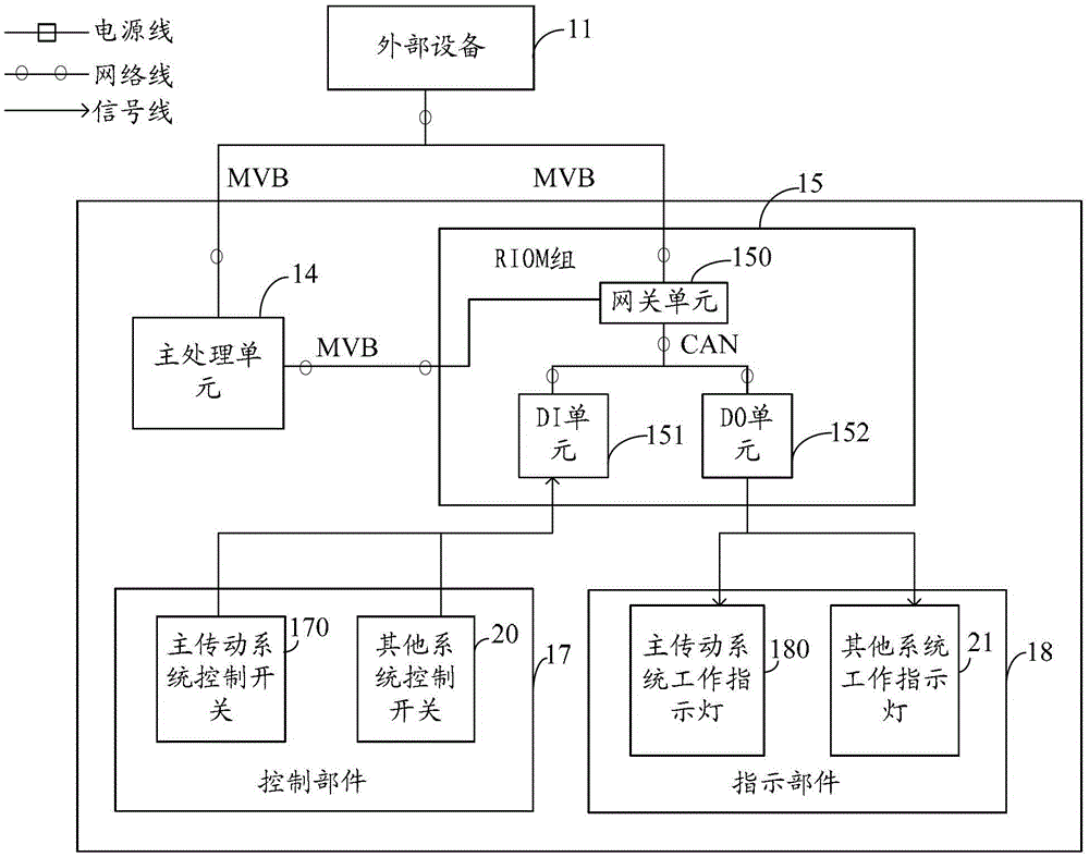
[0028] figure 1 It is a structural schematic diagram of Embodiment 1 of the remote control system used in the locomotive rolling table test of the present invention, as figure 1 As shown, the device of this embodiment may include a console on which a main processing unit 14, a RIOM group 15 and a control unit 17 are arranged; the remote input and output module (RemoteInputOutputModule, hereinafter referred to as: RIOM) group 15 includes a (DigitalInput, hereinafter referred to as DI) unit 151 and gateway unit 150, the control unit 17 includes a main transmission system control switch 170 and other system control switches 20 related to the experiment.

[0029] Further, the main drive system control switch 170 and other system control switches 20 are connected to the DI unit 151, and the DI unit 151 is connected to the gateway unit 150 through a controller area network (ControllerAreaNetwork, hereinafter referred to as CAN) network interface, and the gateway unit 150 is The bus...


PUM


Abstract

This invention provides a remote control system for a locomotive rolling platform test, comprising a control platform on which a main processing unit, an RIOM group and a control part are positioned. The RIOM group comprises a DI unit and a gateway unit; the control part comprises a main transmission system control switch and other system control switches related to the test; the main transmission system control switch and other system control switches are connected to the DI unit; the DI unit is connected to the gateway unit through a CAN circuit; the gateway unit is connected to the main processing unit and an external device through a MVB circuit; and the main processing unit is connected to the external device through the MVB circuit. The remote control system for the locomotive rolling platform test does not need personnel to operate near the device which is malfunctioning during the operation, so that the missing operation and misoperation can be prevented and the test process is simplified and easy to carry out.

Description

technical field [0001] The invention relates to rail transit technology, in particular to a remote control system for locomotive rolling test. Background technique [0002] With the development of the economy, modern society has gradually increased the requirements for railway transport capacity, and the demand for railway locomotives is also increasing. Every locomotive must be tested for line operation before leaving the factory to ensure the running, traction and braking characteristics of the locomotive. realization. Part of the running test of the locomotive needs to be carried out on the main line, so it will put a lot of pressure on the road network. The locomotive fixed rolling test bench is used to control it through a simple and effective method, so that it can exert a specific speed, traction force, and braking force, and test all the characteristic curves of the locomotive, thereby replacing the line test and relieving the pressure on the road network. [0003]...

Claims


Application Information

Patent Timeline
Patent Type & Authority Patents(China)
IPC IPC(8): G05B19/418
CPCY02P90/02
Inventor 董笑辰于跃张小玲裴延涛
Owner CHINA CNR CORPORATION
Why Eureka
Try Eureka